Centrifugal separator

Active Publication Date: 2013-03-21
ALFA LAVAL CORP AB
View PDF97 Cites 15 Cited by
  • Summary
  • Abstract
  • Description
  • Claims
  • Application Information

AI Technical Summary

Benefits of technology

[0013]According to another embodiment of the invention, the drive device is situated outside the space. The drive device is thus isolated from the space which contains polluted gas, which means for example that an electric motor can be protected from a relatively dirty and aggressive environment which contains oil mist, soot and other pollutants.
[0014]According to a further embodiment of the invention, a bearing unit is provided in the delimiting wall of the spac

Problems solved by technology

Such a small annular space may result in flow resistance causing uneven distributi

Method used


Image

  • Centrifugal separator
  • Centrifugal separator
  • Centrifugal separator

Examples


first embodiment

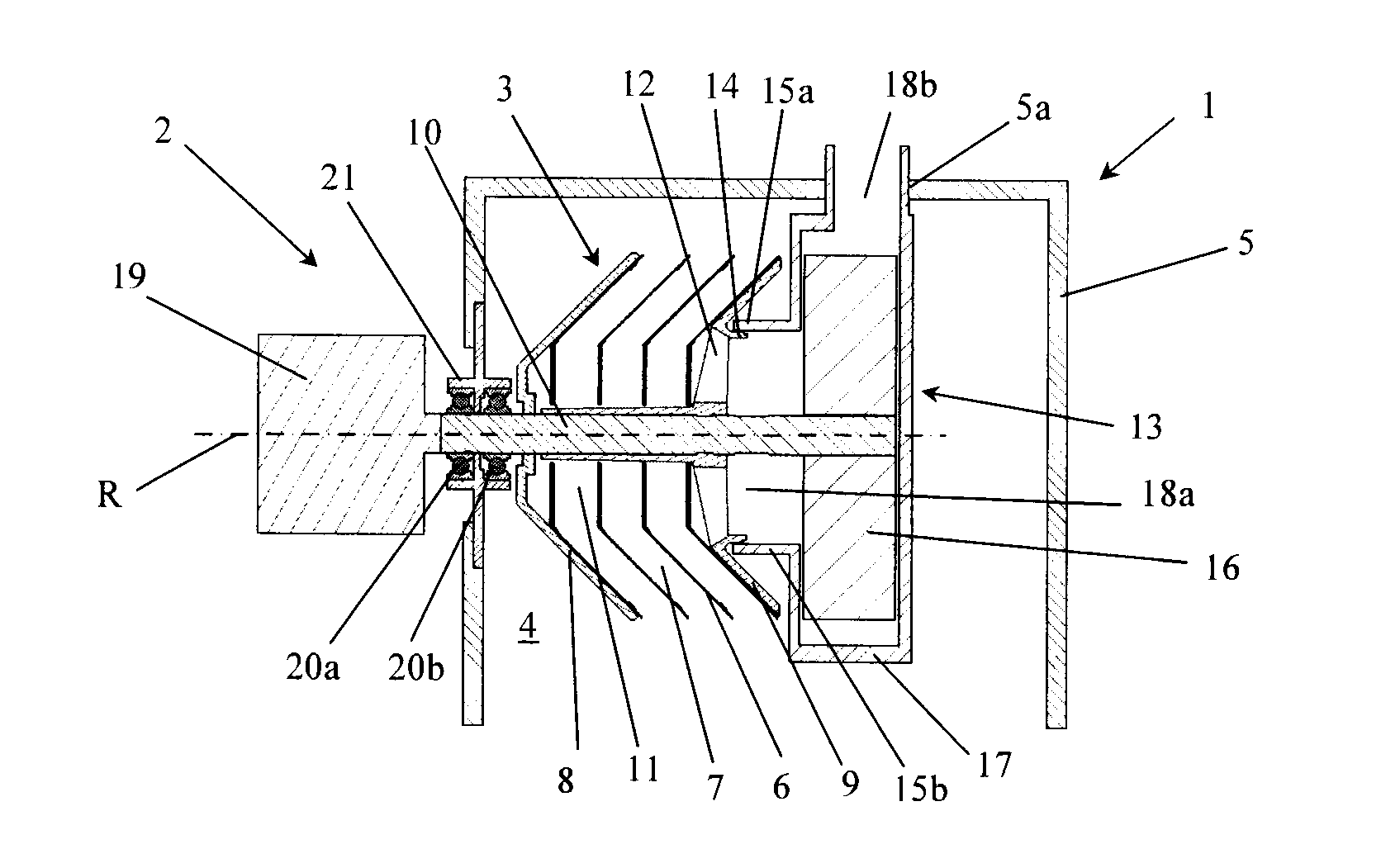
[0033]In the first embodiment shown in FIG. 1, the stationary gas outlet 13 is disposed in the space 4 within the valve cover 5. A fan impeller 16 is provided at a first end of the rotor shaft 10 which extends into the gas outlet 13, and a portion of the gas outlet 13 which surrounds the fan impeller 16 is configured as a fan housing 17. The gas outlet 13 further comprises an outlet duct 18b connected to the fan housing 17 and arranged to conduct crankcase gas out from the space 4 through a duct lead-through or aperture 5a in the valve cover 5. The fan impeller 16 in the gas outlet 13 is configured to pump crankcase gas from the outlet chamber 11 and out through the outlet duct 18b of the fan housing 17. In a counter flow separator, the stack of separating discs 6 exerts a pumping action on the gas flow in a direction opposite to the desired direction of flow, causing flow resistance or pressure drop through such a centrifuge rotor 3 during operation. The fan 16 is thus adapted to a...

second embodiment

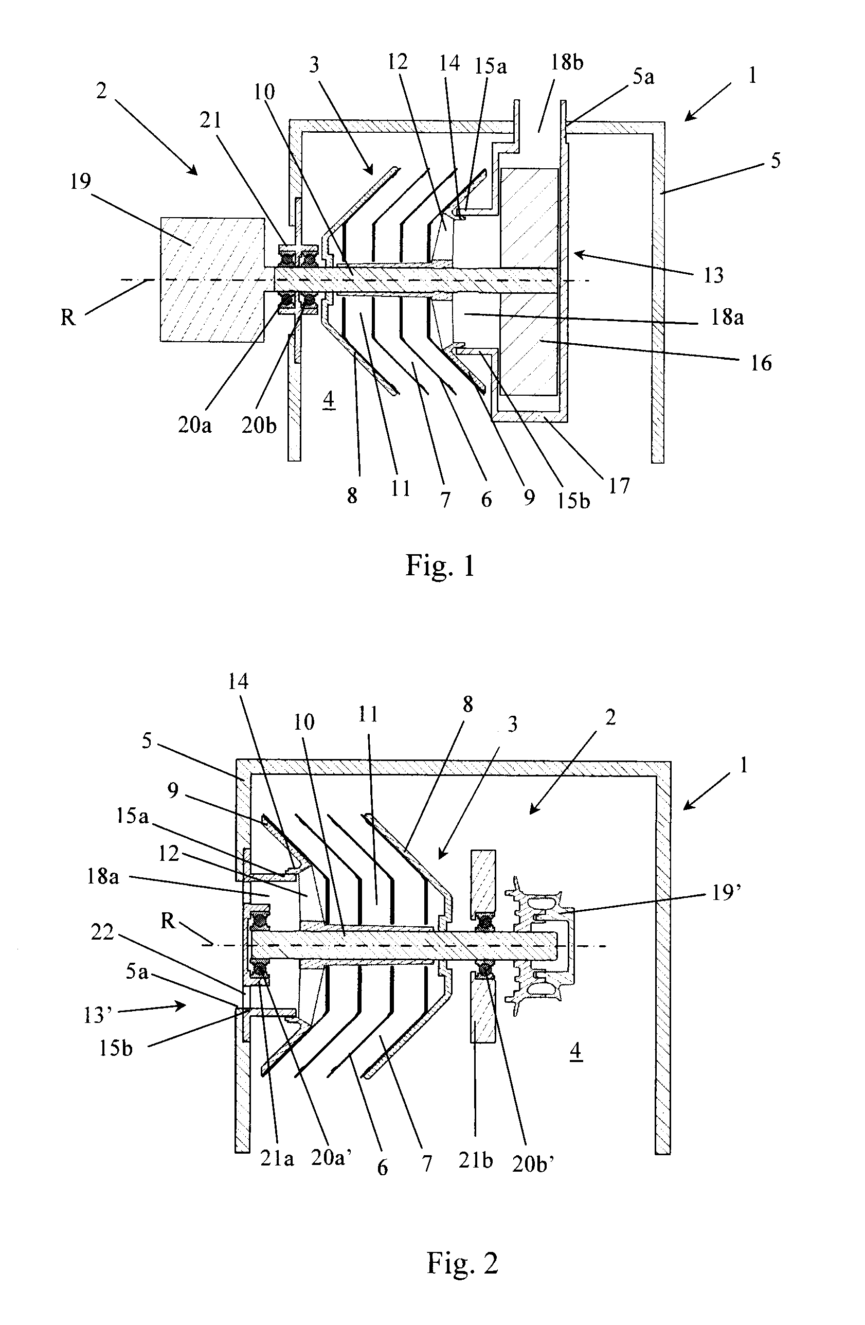
[0035]In the second embodiment shown in FIG. 2, the stationary gas outlet 13′ takes the form of a tubular element 15b which defines an outlet duct 18a for cleaned crankcase gas. In the valve cover 5 there is an aperture 5a to which the outlet duct 18a connects so that cleaned crankcase gas can be conducted out from the space 4 within the valve cover 5. The tubular element 15b is connected directly to the valve cover 5 in the region around its aperture 5a, extends axially inwards towards the annular flange 14 on the second end wall 9 of the centrifuge rotor 3 and has a free end in the form of a cooperating annular flange 15a. As described above, the flanges 14 and 15a are arranged to cooperate in order to guide the cleaned crankcase gas from the central outlet chamber 11 in the centrifuge rotor 3 to the stationary gas outlet 13′.

[0036]FIG. 2 shows a first end of the rotor shaft 10 extending into the tubular element 15b which surrounds a bearing unit comprising a first bearing 20a′ an...

third embodiment

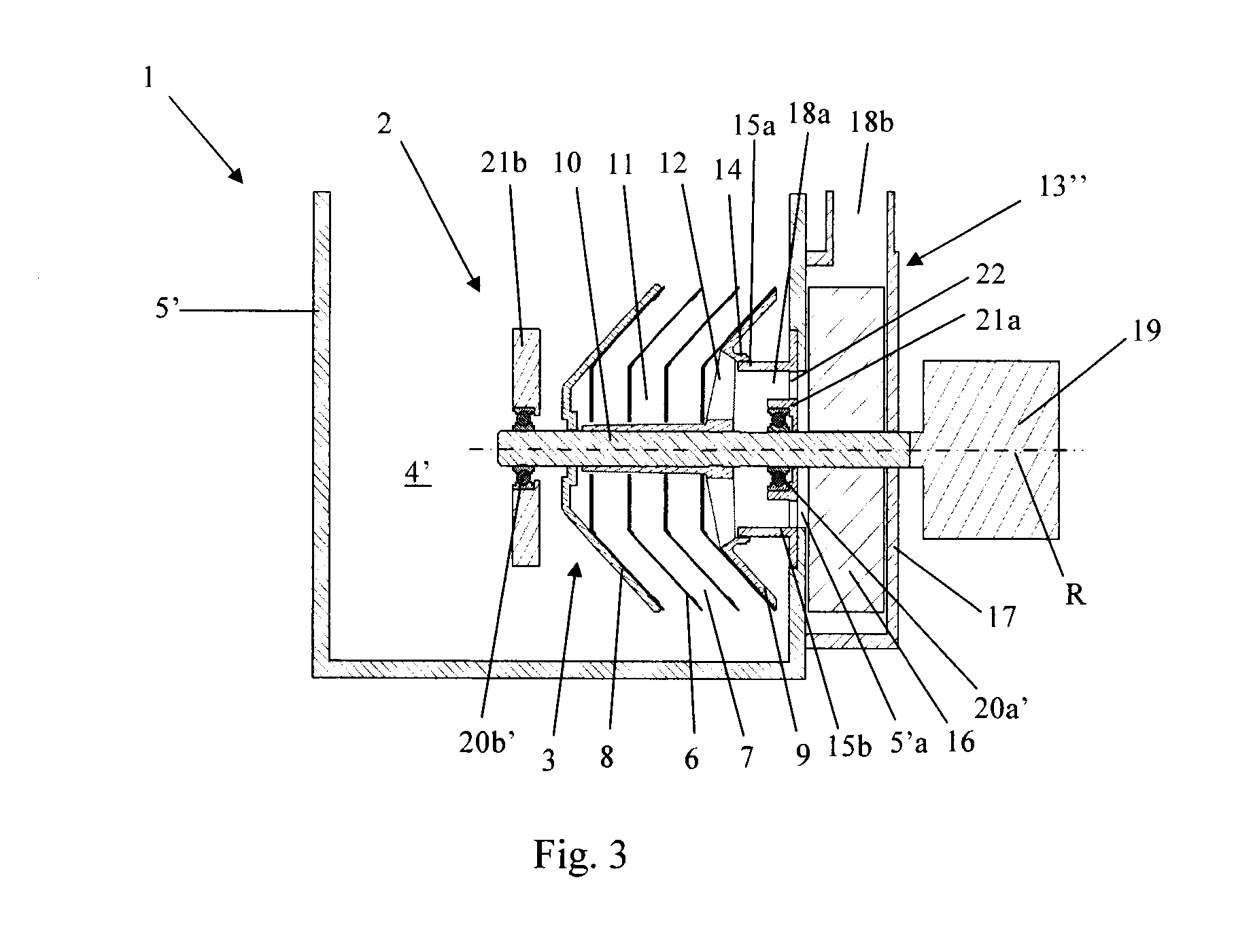
[0037]In the third embodiment shown in FIG. 3, the centrifuge rotor 3 is disposed for rotation within a crankcase 5′. The space 4′ within the crankcase 5′ is arranged to contain oil in liquid form up to a certain level. However, the rotor 3 is disposed in the portion of the space 4′ which is arranged to contain crankcase gas. Consequently, the centrifugal separator 2 shown is situated at a suitable distance above said oil level so that there is no risk of the centrifuge rotor 3 coming into contact with, or being filled with, the liquid oil.

[0038]FIG. 3 shows a stationary gas outlet 13″ provided with a tubular element 15b which defines an outlet duct 18a for cleaned crankcase gas. In the crankcase 5′ there is an aperture 5′a to which the outlet duct 18a connects so that cleaned crankcase gas can be conducted out from the space 4′ within the crankcase 5′. The tubular element 15b is connected directly to the crankcase 5′ in the region round its aperture 5′a and extends radially inwards...


PUM

PropertyMeasurementUnit
Pressure dropaaaaaaaaaa
Speedaaaaaaaaaa

Abstract

A device for cleaning of polluted gas from a combustion engine, includes a centrifugal separator with a centrifuge rotor arranged to cause the polluted gas to rotate. The centrifuge rotor comprises a stack of truncated conical separating discs disposed at mutual spacing so they delimit intermediate spaces between them for the gas to flow through. An outlet chamber is disposed centrally within the stack of separating discs, whereby the centrifuge rotor is configured for counterflow separation. The centrifugal separator comprises a gas outlet which communicates with the outlet chamber. The stack of separating discs is disposed for rotation in a space formed within the combustion engine and arranged to receive the polluted gas, to which end the intermediate spaces between the separating discs communicate directly with the space, and the gas outlet is arranged to conduct the cleaned gas out from the space through a wall which delimits the space.

Description

TECHNICAL FIELD[0001]The present invention relates to a device for cleaning of polluted gas from a combustion engine, e.g. crankcase gas vented from a crankcase of a combustion engine, and in particular to a centrifugal separator for removal of pollutants suspended in the polluted gas in the form of solid or liquid particles.BACKGROUND[0002]Crankcase gas usually contains pollutants in the form of soot particles and / or oil mist.[0003]EP 1273335 B1 describes such a known device for cleaning of crankcase gas. The centrifugal separator of the known device has a stationary housing which delimits within it a chamber in which the centrifuge rotor is arranged to rotate. The centrifugal separator is arranged to be fastened to the side of the combustion engine, and an external feed line is provided to lead crankcase gas from the engine to an inlet provided on the housing and communicating with the centrifuge rotor. During operation, the pollutants are separated from the crankcase gas by the r...

Claims


Application Information

Patent Timeline
IPC IPC(8): F01M13/04B04B9/02B04B5/12B04B5/06
CPCB04B5/005B04B5/08B04B5/12B04B9/12B04B9/02F01M13/04F01M13/0416F01M2013/0422B04B5/06B04B2005/125B04B5/00B01D45/14B04B1/08
Inventor SZEPESSY, STEFANTORNBLOM, OLLE
Owner ALFA LAVAL CORP AB
Why Eureka
Try Eureka