Lens driving device for optical read and/or write system and optical read/write system

a driving device and optical read/write technology, applied in the direction of instruments, head carrier disposition/mounting, maintaining head carrier alignment, etc., can solve the problems of system instability, uncontrollable, and inability to design a simple system in practice, so as to improve high frequency characteristics and reduce one or more of the indicated problems

Inactive Publication Date: 2005-10-27
KONINKLIJKE PHILIPS ELECTRONICS NV
View PDF4 Cites 5 Cited by
  • Summary
  • Abstract
  • Description
  • Claims
  • Application Information

AI Technical Summary

Benefits of technology

[0006] It is an object of the invention to provide a lens driving device of the type described in the opening paragraph and an optical read and / or write system comprising a lens driving device with improved high frequency characteristics to reduce one or more of the indicated problems.

Problems solved by technology

However, the combinations of resonances and anti-resonances as described above are a limit to this bandwidth.
In the case of these resonance and anti-resonance combinations, it is not possible in practice to design a simple (PID or PI-lead / lag) feedback controller, such that the total system has a loop gain that is smaller than 1 for the frequency where the phase is −180°, while the bandwidth of this system is in the region of the resonance / anti-resonance peaks.
That is, if the loop gain comes close to −1, the system gets unstable and uncontrollable.
Thus there is a tendency that the upper limit in the servoband of the control system increases, leading to a need to increase the natural resonance frequency of the mechanical structure.
This makes it often difficult to reach very high resonance frequencies, because of limitations on the space that can be occupied by the mechanical structure, or notwithstanding an increase of the natural resonance frequency, the increase of read / write speed also increases the upper limit (in frequency) of the servocontrol to a frequency approaching a natural resonance frequency.

Method used


Image

  • Lens driving device for optical read and/or write system and optical read/write system
  • Lens driving device for optical read and/or write system and optical read/write system
  • Lens driving device for optical read and/or write system and optical read/write system

Examples


second embodiment

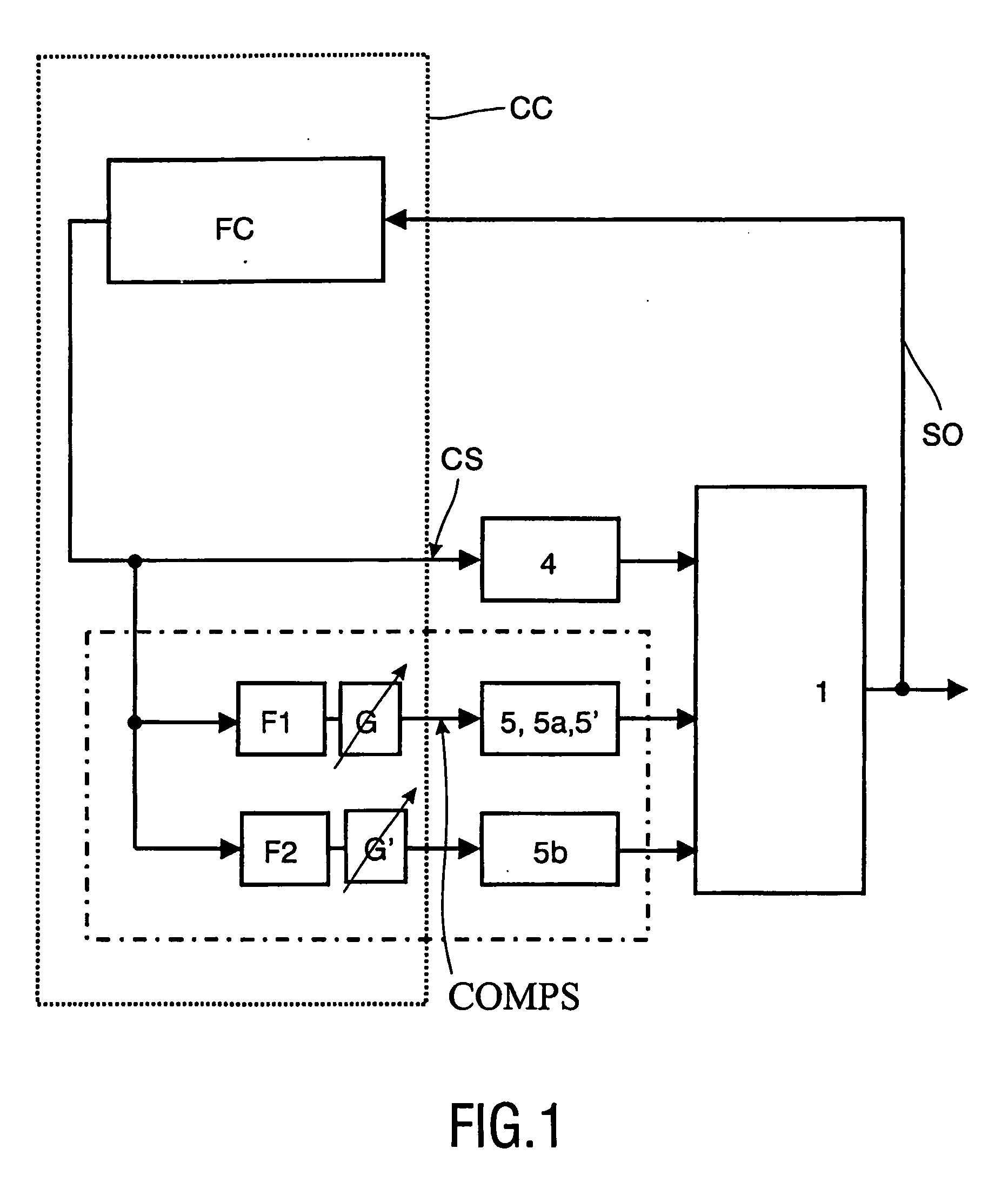
[0029]FIG. 3. shows a This embodiment comprises the same mechanical structure as shown in FIG. 2, except that the piezo-electric element 5 is divided into two separate zones 5a, 5b. By feeding these separate zones 5a, 5b through different filters i.e. at different frequency ranges (see FIG. 1) and / or by designing them in such a way that more resonances are excited, more than one resonance can be compensated.

third embodiment

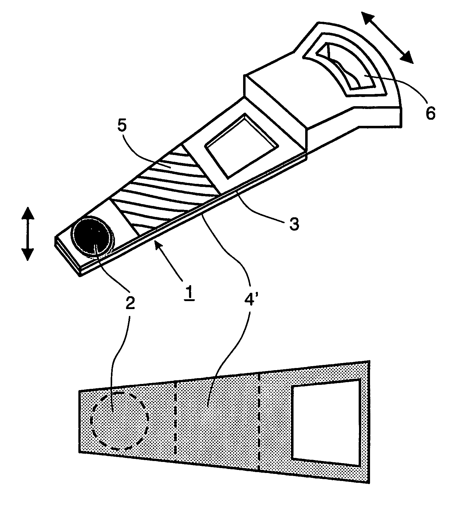
[0030]FIG. 4 shows yet a third embodiment, similar to the embodiment shown in FIG. 2, except that focus movement is not generated by a coil 4, but by a thin piezo-electric element 4′, for instance, glued on the bottom of the mechanical structure 2. The combination of piezo-electric elements 5 and 4′ makes the structure thinner and smaller, which in itself is an advantage. It is noted that the invention is to be understood to offer a route for reducing problems with resonances. The invention is not to be so restrictively interpreted as being unable to be combined with other measures of reducing problems with resonances. For instance, making the mechanical structure thinner and lighter (as in the example of FIG. 4) reduces the weight, thereby reducing power consumption. It may also lead to an increase of the resonance frequency, which is an advantage.

[0031]FIG. 5 shows yet a further embodiment of a lens driving device in accordance with the invention. It comprises the same actuators a...

fifth embodiment

[0032] A fifth embodiment is shown in FIG. 6. It comprises a lens 2 on a mechanical structure comprising a lens holder 3a, hinges 3b and a base 3c. The focusing and radial movements are generated by electromagnetic actuators of which only the permanent magnet system 7 and the radial coils 8 are shown. The resonance of the hinges during the focusing movement are reduced (compensated) by piezo-elements 9 on top of the hinges, while the resonances during radial movement are suppressed by piezo-electric elements 10.

[0033] Finally, FIGS. 7A and 7B illustrate in a graphical form the effect of the invention. In this graph, experimental results are shown for an embodiment as schematically shown in FIG. 2. The horizontal axis denotes the frequency, whereas in the vertical direction gain (ratio of SO / CS in dB) is given (FIG. 7A), and the phase difference. Two lines are drawn, one (the solid line) without use of a compensating actuator, the other (the dotted line) with use of a compensating ac...


PUM

PropertyMeasurementUnit
frequenciesaaaaaaaaaa
resonance frequenciesaaaaaaaaaa

Abstract

A lens driving device (1) or an optical read and/or write system comprises a mechanical structure (3) with an objective lens (2) and an actuator (4, 4′, 6) for controlling the lens position. The lens driving device comprises a further actuator (5, 5a, 5b, 5′) on or near the mechanical structure so as to at least partially compensate motion generated by the first-mentioned actuator (4,6).

Description

FIELD OF THE INVENTION [0001] The invention relates to a lens driving device for an optical read and / or write system, comprising a mechanical structure having an objective lens, and an actuator for controlling the lens position by acting on the mechanical structure. [0002] The invention also relates to an optical read and / or write system comprising a lens driving device comprising a mechanical structure having an objective lens, and an actuator for controlling the lens position by acting on the mechanical structure, the system further comprising a controller means for generating a control signal for the actuator, the actuator acting in response to the control signal. BACKGROUND OF THE INVENTION [0003] Lens driving devices as well as optical read and / or write systems comprising lens driving devices are known. An optical read and / or write system reads information recorded on an optical medium, e.g. on a disk, using laser light to read / write a signal optically and / or write information ...

Claims


Application Information

Patent Timeline
Patent Type & Authority Applications(United States)
IPC IPC(8): G11B5/55G11B5/56G11B5/58G11B7/00G11B7/085G11B7/09G11B7/12G11B11/10G11B13/04
CPCG11B5/5552G11B5/5556G11B5/58G11B7/1203G11B7/0937G11B7/0941G11B7/0946G11B7/08576G11B7/122
Inventor GOOSSENS, HENDRIK JOSEPHUSCLOOSTERMAN, MARIA BERNARDINA GERTRUDA
Owner KONINKLIJKE PHILIPS ELECTRONICS NV
Why Eureka
Try Eureka