Patch Antenna with a Ceramic Plate as a Cover

a technology of ceramic plate and cover, applied in the direction of liquid/fluent solid measurement, waveguide horn, instruments, etc., can solve the problems of antenna filling or seal, inability to meet the requirements of high temperature, and inability to achieve, so as to reduce the soiling of the exterior region of the process separation device.

Active Publication Date: 2007-12-06
VEGA GRIESHABER GMBH & CO
View PDF11 Cites 12 Cited by
  • Summary
  • Abstract
  • Description
  • Claims
  • Application Information

AI Technical Summary

Benefits of technology

[0027] In this way soiling of the exterior region

Problems solved by technology

Plastics that are used in known sensors as antenna fillings or seals are above all unable to withstand the high temperatures.
If these plastics are to be replaced by ceramics or glass, then due to the high relative permittivities ∈r of the ceramics and of the glass this may not be achieved without further ado especially in the case of higher transmission frequencies of th

Method used


Image

  • Patch Antenna with a Ceramic Plate as a Cover
  • Patch Antenna with a Ceramic Plate as a Cover
  • Patch Antenna with a Ceramic Plate as a Cover

Examples


Embodiment Construction

[0052] In the following description of the figures the same reference characters are used for identical or similar elements.

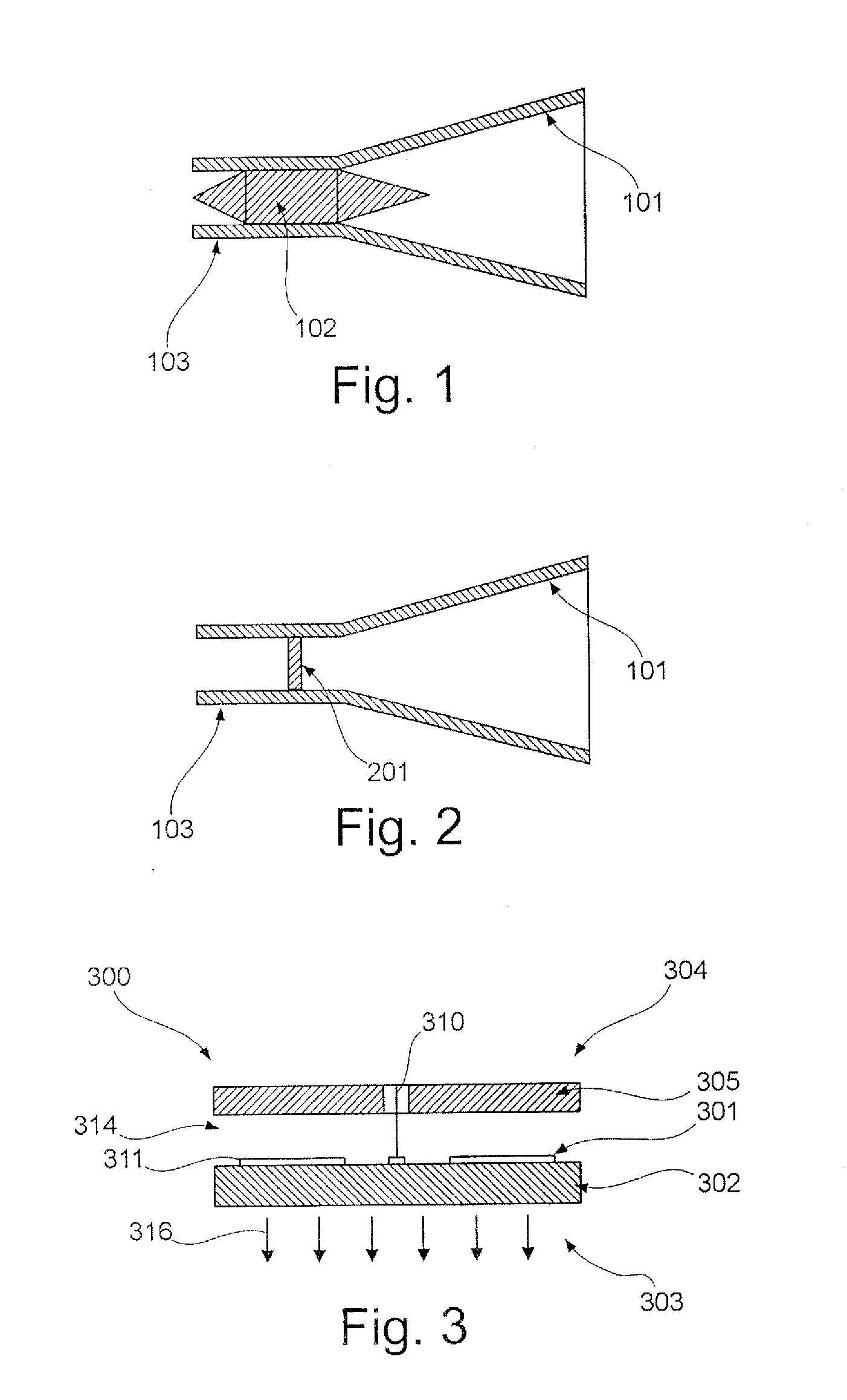
[0053]FIG. 1 shows a diagrammatic view of a horn antenna 101 with an adaptor cone 102 made of a dielectric material. In this arrangement the electromagnetic transmission signal is introduced into the horn antenna 101 by way of the hollow conductor 103 and the adaptor cone 102 and is then radiated to the feed material. If the adaptor cone from a dielectric material 102 is to be designed as a process separation device for high temperatures and high pressures, it has to comprise a corresponding temperature resistance and pressure resistance. It must thus not be made of plastic material as it would melt at elevated temperatures. However, if the adaptor cone 102 is made from temperature-resistant materials such as ceramics or glass, this can result in problems during signal transmission due to the high relative permittivity of the materials ceramics or glass. As a ...


PUM


Abstract

Described is a planar antenna with a process separation device for a fill level radar. The planar antenna including a plate-shaped temperature-resistant process separation device that is arranged between the planar radiator element and the exterior of the antenna.

Description

REFERENCE TO RELATED APPLICATIONS [0001] This application claims the benefit of the filing date of German Patent Application Serial No. 10 2006 019 688.0 filed Apr. 27, 2006 and U.S. Provisional Patent Application Ser. No. 60 / 795,618 filed Apr. 27, 2006, the disclosure of which applications is hereby incorporated herein by reference.FIELD OF THE INVENTION [0002] The present invention relates to fill level measuring. In particular the present invention relates to a planar antenna with a process separation device for a fill level radar, to a fill level radar with a planar antenna, and to the use of such a planar antenna for fill level measuring. BACKGROUND INFORMATION [0003] In fill level measuring technology there are numerous applications in which a high temperature or a high pressure is present. The process temperature may, for example, be up to 400° C. The pressure can have a value of up to 160 bar or more. [0004] To make it possible in these applications to read the fill level wi...

Claims


Application Information

Patent Timeline
IPC IPC(8): H01Q13/00H01Q13/02
CPCG01F23/284H01Q21/065H01Q13/02H01Q1/22H01Q1/225
Inventor SCHULTHEISS, DANIELMOTZER, JUERGENFEHRENBACH, JOSEF
Owner VEGA GRIESHABER GMBH & CO
Why Eureka
Try Eureka