Gas flow indicator

a flow indicator and gas technology, applied in the direction of signalling system, respiratory device testing, instruments, etc., can solve the problems of not receiving the required level of oxygen and the patient is not effectively ventilated, so as to reduce running costs and ensure the effect of gas

Inactive Publication Date: 2013-03-21
SWANSEA UNIV
View PDF15 Cites 21 Cited by
  • Summary
  • Abstract
  • Description
  • Claims
  • Application Information

AI Technical Summary

Benefits of technology

[0007]Embodiments of the present invention therefore provide a simple and effective mechanism for quickly detecting if gas is flowing as it should through medical equipment. Importantly, any person monitoring the gas flow need not look at the gas flow indicator in order to know whether or not the gas is flowing as it should. Instead, those people may be busy with other tasks, safe in the knowledge that they will be alerted to any potential problems by an audible sound (or lack thereof). Moreover, the audible sound generated by the gas flow indicator will enable a listener to quickly detect the location of a potential problem by following the sound to its source.
[0016]In other embodiments, the medical equipment may be constituted by an oxygen enrichment device. The oxygen enrichment device may comprise a reservoir configured to receive oxygen flowing from an oxygen cylinder through a first inlet, a second inlet which is open to the air and an outlet arranged to provide a mixture of air from the second inlet and oxygen from the reservoir to the patient through a suitable tube or mask. The reservoir may be configured as a rigid (e.g. cigar-shaped) component or a flexible component, such as a bag. The gas flow indicator may be located in the first inlet and may be arranged to provide an audible indication when gas is correctly flowing from the cylinder into the reservoir. Accordingly, the lack of an audible sound will indicate that there is a problem with the oxygen supply. For example, the cylinder may be empty (which happens quite often since relatively small cylinders are employed to make them easily portable), or the cylinder may not have been set correctly (e.g. the gas supply may be turned off or not set to deliver the desired flow rate). In each of the above cases, the result is that not enough oxygen is flowing into the reservoir for inhalation by the patient. As a consequence, the patient will be breathing in a hypoxic mixture not containing sufficient oxygen. Moreover, the patient may be re-breathing their own expressed air containing progressively decreasing concentrations of oxygen and progressively increasing concentrations of carbon dioxide. Thus, the gas flow indicator in this embodiment can quickly alert staff to the fact there is a problem with the oxygen supply even if the bag is inflating and deflating, as expected.
[0018]This would therefore help staff to determine that the correct flow rate had been selected. It might also help to ensure that gas is not wasted by employing a higher than necessary flow rate. Consequently, running costs could be reduced.

Problems solved by technology

However, it is not uncommon for an anaesthetist to forget to reconnect or close the sampling port, causing gases to escape from the open sampling port so that the patient is not effectively ventilated.
However, if the oxygen cylinder is empty, disconnected or delivering oxygen at an incorrect flow rate, the patient may still be breathing regularly (and the bag inflating and deflating accordingly) but they will not be receiving the required level of oxygen.
Moreover, they may, in fact. be re-breathing their own expressed air which is highly undesirable since it results in the patient obtaining progressively decreasing concentrations of oxygen and progressively increasing concentrations of carbon dioxide.

Method used


Image

  • Gas flow indicator
  • Gas flow indicator
  • Gas flow indicator

Examples


first embodiment

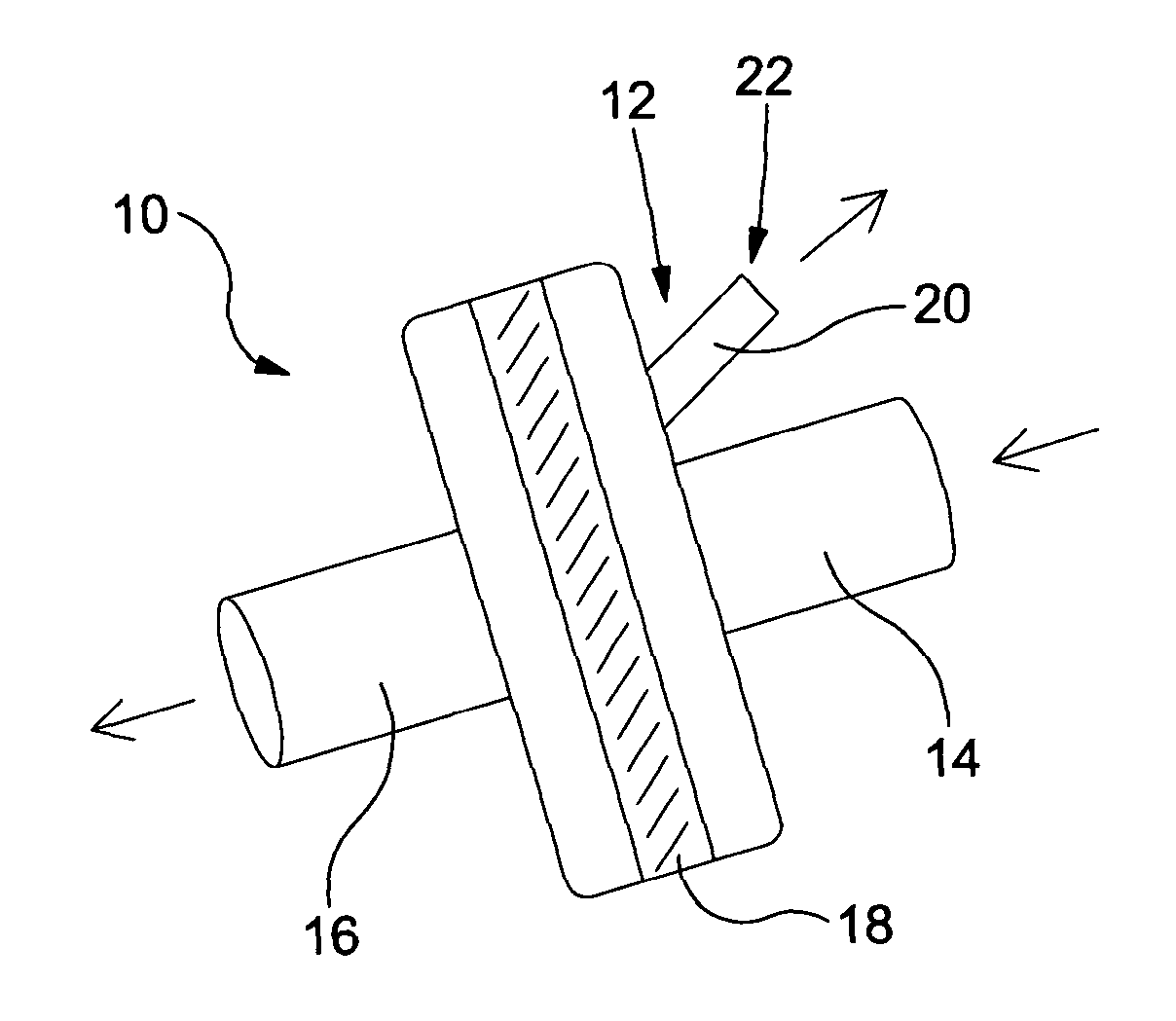
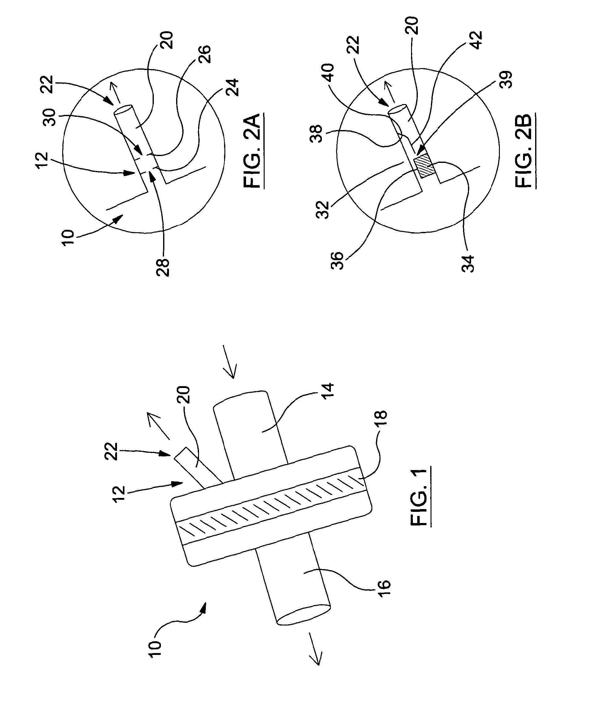
[0034]With reference to FIG. 1, there is illustrated a heat moisture exchanger (HME) 10 comprising a gas flow indicator 12 in accordance with the present invention. The heat moisture exchanger 10 comprises a cylindrical inlet 14 for connection to a gas supply, a cylindrical outlet 16 for connection to an endotracheal tube or laryngeal mask, and a filter 18 therebetween. The filter 18 is configured to trap heat and moisture on exhalation and to return heat and moisture on inhalation.

[0035]A cylindrical sampling port 20 is provided adjacent the inlet 14 and, in this instance, the gas flow indicator 12 is housed within the sampling port 20 and is configured to provide an audible indication when gas is exiting the HME 10 through the sampling port 20 and into the atmosphere.

[0036]It will be understood that the HME 10 is configured as a single use disposable item to avoid the need for sterilisation between subsequent uses.

[0037]In use, the inlet 14 is connected to an anaesthetic machine f...

second embodiment

[0045]FIG. 4 shows the present invention in which a gas flow indicator 90 is incorporated into a rigid oxygen enrichment device 92. The oxygen enrichment device 92 comprises a generally cigar-shaped reservoir 94 configured to receive oxygen flowing from an oxygen cylinder through a first inlet 96, a second inlet 98 which is open to the air and a patient outlet 100 which connects to a patient via a suitable tube or mask and which is arranged to provide a mixture of air and oxygen to the patient through the tube or mask. The reservoir 94 has an open end 101, opposite to the first inlet 96, which allows excess gas to flow out of the device 92. On inspiration, the first part of the breath will mainly comprise oxygen from within the reservoir 94 and the second part of the breath will mainly comprise air from the open end 101 and the second inlet 98.

[0046]The gas flow indicator 90 is located in path of the first inlet 96 although it is actually disposed in an extension 102 to the first in...

third embodiment

[0048]FIG. 5 shows the present invention in which a gas flow indicator 110 is incorporated into an oxygen enrichment device 112 which is similar to that shown in FIG. 4 but wherein the reservoir is constituted by a flexible bag 114. The oxygen enrichment device 112 therefore comprises an elongate bag reservoir 114 configured to receive oxygen flowing from an oxygen cylinder through a first inlet 116, a second inlet 118 which is open to the air and an outlet 120 arranged to provide a mixture of air from the second inlet 118 and oxygen from the reservoir 114 to a patient through a suitable tube or mask.

[0049]As shown in FIG. 6, the gas flow indicator 110 is located in path of the first inlet 116 before the path of the first inlet 116 crosses the path between the second inlet 118 and the outlet 120. In other embodiments, the gas flow indicator 110 may be located in the path of gas flowing through the first inlet 116 and in the path of gas flowing though the second inlet 120 so that the...


PUM


Abstract

A gas flow indicator (12) for medical equipment is described which is configured to provide an audible indication of gas flow. The medical equipment may be in form of a respiratory care device, an airway management device, a heat moisture exchanger (10), an oxygen enrichment device (92,112) or a breathing mask (132).

Description

FIELD OF THE INVENTION[0001]This invention relates to a gas flow indicator. Particularly, but not exclusively, the invention relates to a gas flow indicator for use in medical equipment such as that employed in respiratory care and airway management (for example, in equipment used for the delivery of gases to and from a patient).BACKGROUND OF THE INVENTION[0002]There are many instances when it is desirable to monitor a patient's breathing and / or the gases they are inhaling or exhaling. For example, a patient may be administered with a general anaesthetic prior to a surgical procedure. In this case, the anaesthetic may be provided in the form of a gas which is delivered to the patient through a mask or tube inserted via the patient's mouth or nose and into their trachea. In some cases, patients are anaesthetised in an anaesthetic room before being transferred to a separate surgical theatre and so it is necessary for the patient to be disconnected from the anaesthetic equipment in the...

Claims


Application Information

Patent Timeline
Patent Type & Authority Applications(United States)
IPC IPC(8): A61M16/00
CPCA61M16/0051A61M16/06A61M16/0875A61M16/1045A61M2016/003A61M16/101A61M2205/186A61M2205/43A61M2205/44A61M2205/581A61M2205/183A61M16/085
Inventor MIAN, OMARMIAN, TANWIR MUHAMMED
Owner SWANSEA UNIV
Why Eureka
Try Eureka