Bottom-adjustable propeller-type flying object

a flying object and bottom-adjustable technology, applied in the field of bottom-adjustable propeller-type flying objects, can solve the problems of low power efficiency, easy breakage of bottom-adjustable blade-type flying objects according to the related art, complex structure and complex adjusting devices, etc., and achieve the effect of simplifying the structure, size and weight of the bottom-adjustable propeller-type flying obj

Inactive Publication Date: 2013-03-21
SUNTECH ENTERPRISES
View PDF15 Cites 20 Cited by
  • Summary
  • Abstract
  • Description
  • Claims
  • Application Information

AI Technical Summary

Benefits of technology

[0011]As described above, according to the present invention, the bottom-adjustable propeller-type flying object can control the anti-torque, make the hovering flight, the leftward and rightward rotation, and the forward and backward flights by using two adjusting motors having adjustable propellers mounted thereon.
[0012]In addition, according to the present invention, the failure and the breakdown caused by the combination of several components of a flying object according to the related art can be reduced by simplifying the structure and the adjustment of the bottom-adjustable propeller-type flying object. In addition, since the size and the weight of the bottom-adjustable propeller-type flying object can be reduced, the power efficiency of the bottom-adjustable propeller-type flying object can be enhanced. Further, the duration of the flight of the bottom-adjustable propeller-type flying object can be increased.

Problems solved by technology

The bottom-adjustable propeller-type flying object according to the related art has a complex structure and complex adjusting devices, and represents low power efficiency due to the variation of the pitch angle of the rotor.
Accordingly, the bottom-adjustable blade-type flying object according to the related art may be easily broken and may have a disadvantage in the management thereof.
In addition, the volume and the weight of the bottom-adjustable blade-type flying object are increased due to the combination of several components, so that the power efficiency is degraded.

Method used


Image

  • Bottom-adjustable propeller-type flying object
  • Bottom-adjustable propeller-type flying object
  • Bottom-adjustable propeller-type flying object

Examples


Embodiment Construction

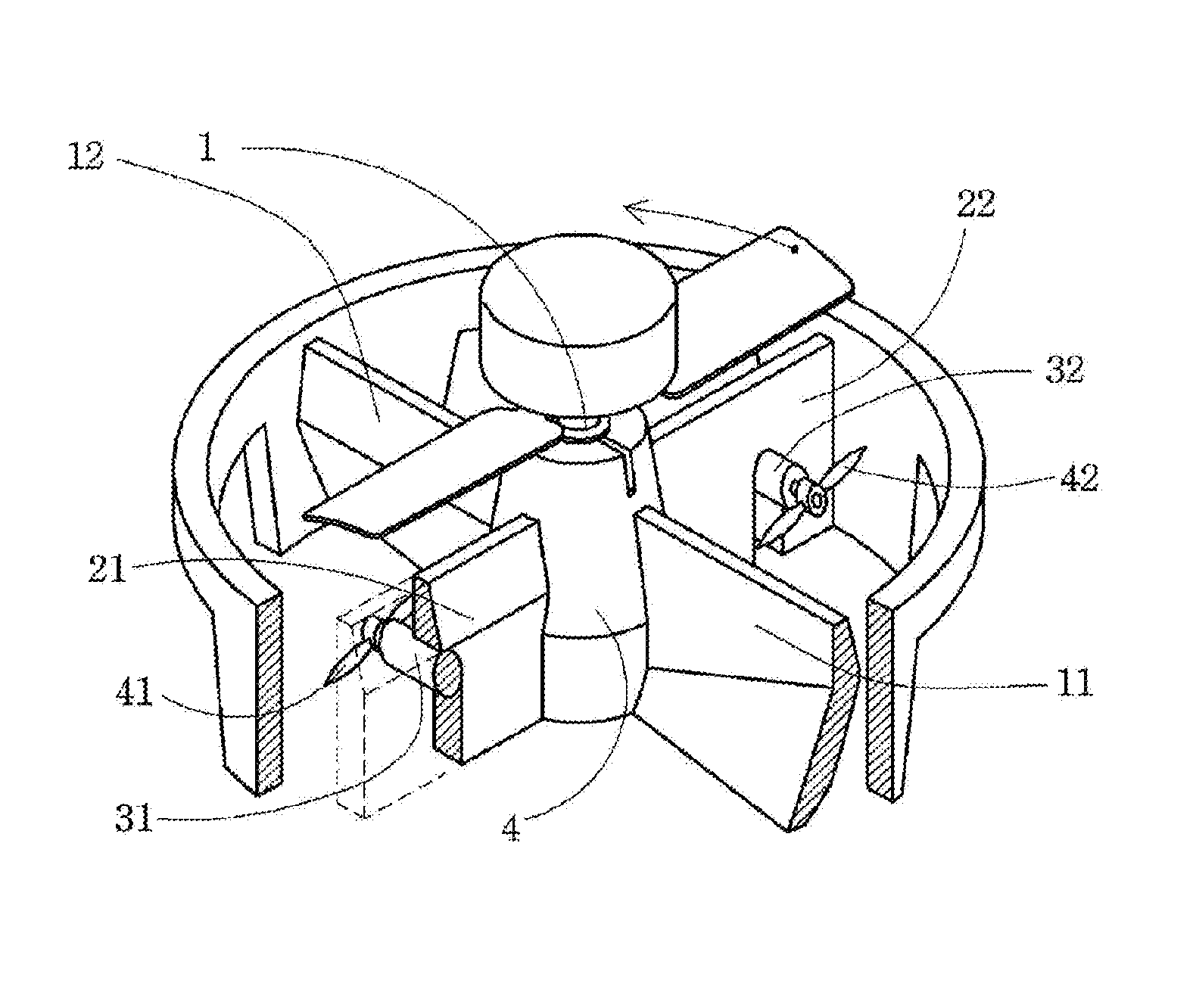
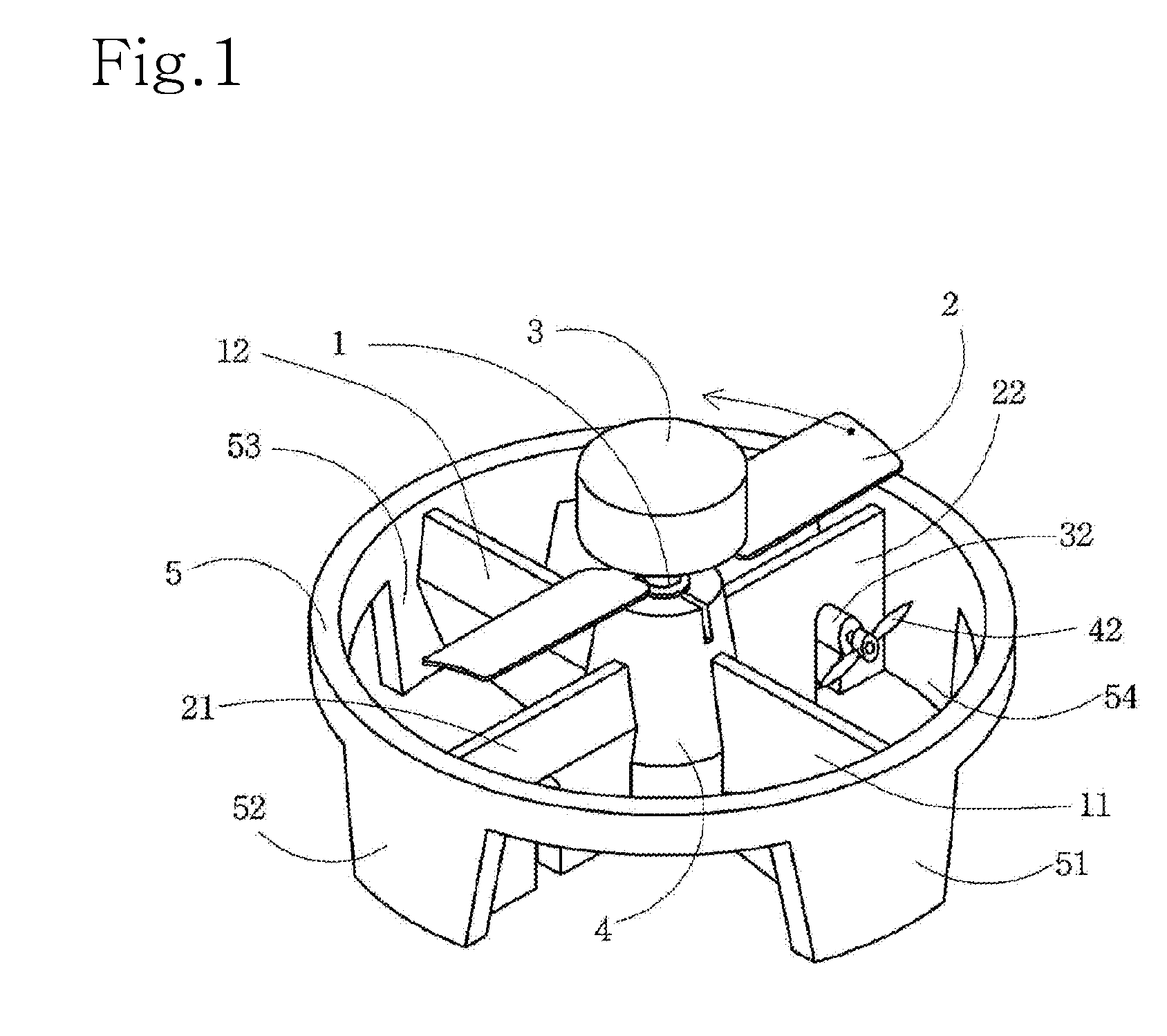
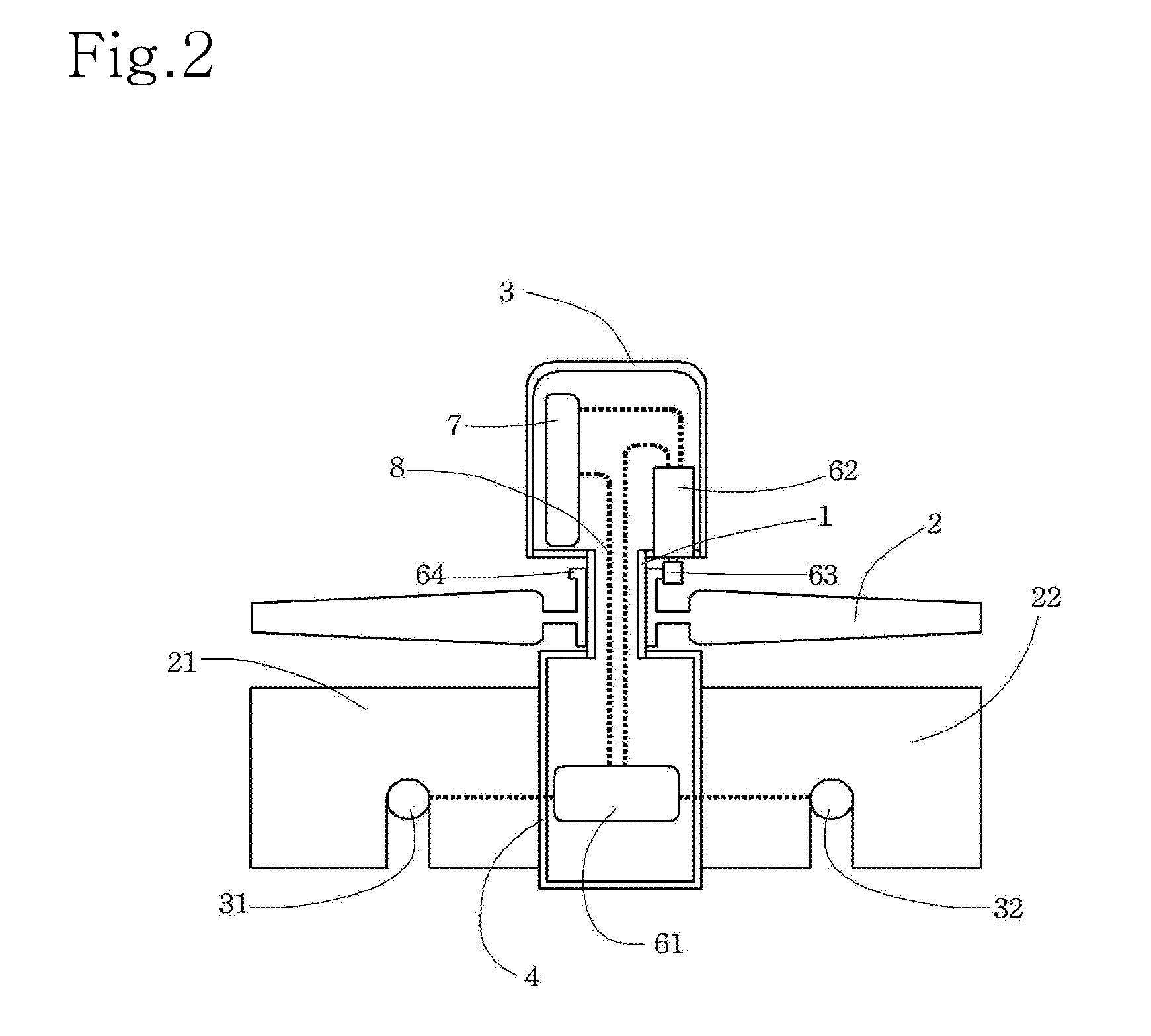
[0017]Hereinafter, in order to accomplish the above object, the structure of the present invention will be described with reference to FIG. 1, which is a perspective view of the present invention, FIG. 2, which is a longitudinal sectional view of FIG. 1 without a circular frame 5 and leg plates 51, 52, 53, and 54 of FIG. 1, and FIG. 3 which is a partially-cut perspective view of FIG. 1.

[0018]A bottom-adjustable propeller-type flying object according to the present invention includes a fixed pitch power propeller 2 mounted on an outer circumference of a central shaft 1 having the shape of a hollow cylindrical pipe and having a plurality of blades, a power unit 3 mounted on the upper portion of the central shaft 1, a controller 4 mounted on the lower portion of the central shaft 1, first and second fixing plates 11 and 12, first and second protective plates 21 and 22, a circular frame 5 having the shape of a circular ring, leg plates 51, 52, 53, and 54, and first and second adjustable...


PUM


Abstract

An existing bottom-adjustable propeller-type flying object requires a device having a complex structure constructed through the combination of various components such as a servo, a control plate, and a hinge to control the rotor pitch at every moment and operate an adjustable blade for flight control. The bottom-adjustable propeller-type flying object of the disclosure includes a circular frame with a fixing plate and a protective plate installed at a lower portion of a shaft of a power propeller mounted to the central shaft, and an adjusting motor having an adjustable propeller. The flying object moves up or down by using force of the wind generated downward due to the rotation of the power propeller. The flying object makes a hovering flight, and leftward, rightward, forward, and backward flights by using the force of the wind generated due to the rotation of the adjustable propellers mounted on two adjusting motors.

Description

TECHNICAL FIELD [0001]The present invention relates to a bottom-adjustable propeller-type flying object. In more particular, the present invention relates to a bottom-adjustable propeller-type flying object acting as a flying object having small bottom blades, which is one type of an unmanned rotor craft.BACKGROUND ART[0002]In general, a bottom-adjustable propeller-type flying object according to the related art includes a rotor or a propeller, which rotates about the central shaft of the flying object by a driving force, a power part, a controller, a fixing plate, and adjustable blades. The bottom-adjustable propeller-type flying object makes a flight by operating an adjustable blade for the removal of anti-torque provided at the lower portion of the propeller.[0003]The bottom-adjustable propeller-type flying object according to the related art maintains the balance thereof by adjusting the pitch of the rotor using a sensor or a stable bar whenever the bottom-adjustable propeller-t...

Claims


Application Information

Patent Timeline
Patent Type & Authority Applications(United States)
IPC IPC(8): B64C27/82
CPCA63H27/12B64C39/024B64C2201/027B64C27/20B64C2201/165B64C27/82B64C2201/108B64U10/13B64U30/20B64U50/13
Inventor CHOI, KEY DONGCHOI, KEY NAM
Owner SUNTECH ENTERPRISES
Why Eureka
Try Eureka