Electronically controlled universal motor

a universal motor and electric motor technology, applied in the direction of motor/generator/converter stopper, control/drive circuit, dynamo-electric converter control, etc., can solve the problems of loss of efficiency when operated at different speeds, significant drawbacks of coupling the required waveform to the rotor winding arrangement, and achieve the effect of simplifying manufacturing/maintenance and facilitating cooling of the rotor winding control uni

Active Publication Date: 2013-03-21
ARM LTD
View PDF3 Cites 13 Cited by
  • Summary
  • Abstract
  • Description
  • Claims
  • Application Information

AI Technical Summary

Benefits of technology

[0018]Accordingly an electric motor apparatus is provided which is configured as a universal motor, that is to say wherein both the rotor component and the stator component have respective winding arrangements. Further, there is provided a rotor winding control unit fixedly mounted on the rotor component, i.e. such that the rotor winding control unit rotates with the rotor component as part thereof. This rotor winding control unit performs a rotor waveform generation operation in order to generate the rotor waveform which is applied to the rotor winding arrangement. The rotor winding arrangement generates this rotor waveform from a rotor supply voltage which is supplied to the rotor component. Accordingly, the need for the commutators or numerous slip rings of the prior art is avoided, since only the externally supplied rotor supply voltage needs to be coupled to the rotor component. This means that the noise and inefficiency associated with a commutator and the manufacturing complexity associated with numerous slip rings are each avoided.
[0034]In one embodiment said control unit is mounted on an axial face of said rotor component. Although the rotor winding control unit could in principle be mounted in a number of different ways in or on said rotor component, mounting the rotor winding control unit on an axial face of said rotor component facilitates cooling of the rotor winding control unit as well as simplifying manufacturing / maintenance.

Problems solved by technology

Such DC motors are known to be relatively powerful but suffer from the magnetic drag of the permanent magnet mounted on the rotor and thereby lose efficiency.
Induction motors are known to be very efficient at a given design speed, but lose efficiency when operated at different speeds.
However, the difficulties associated with coupling the required waveforms to the rotor winding arrangements have significant drawbacks.
However, powering the rotor windings 20 is not as simple as powering the stator windings 30 due to the rotation of the rotor.
However commutators are relatively primitive mechanical connectors which tend to be both noisy and inefficient.
However, due to the number of separate electrical connections that are typically required, and the corresponding number of slip rings which must then also be provided, considerable manufacturing complexity is associated with a rotor comprising numerous slip rings and also with its shaft with a corresponding number of concentric power channels (typically layered on the shaft).

Method used


Image

  • Electronically controlled universal motor
  • Electronically controlled universal motor
  • Electronically controlled universal motor

Examples


Embodiment Construction

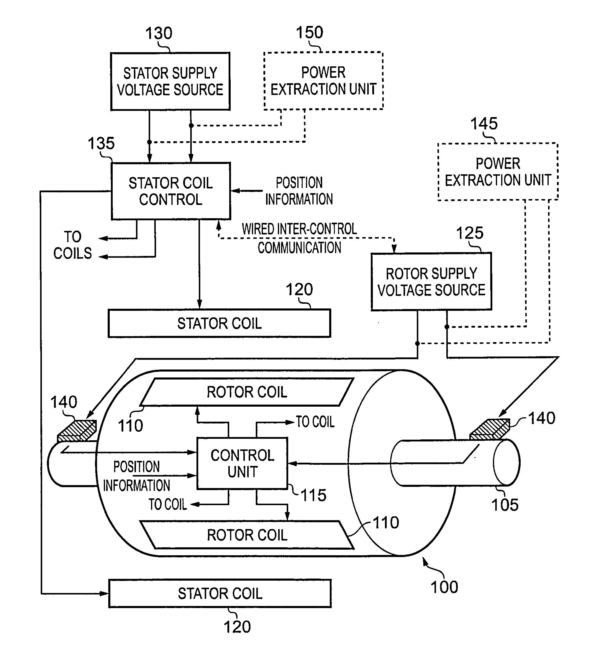
[0073]FIG. 5 schematically illustrates an electric motor apparatus in one embodiment. The rotor 100, configured to rotate on axle 105, has, a set of rotor coils 110 arranged around its circumference (of which only two are explicitly illustrated). The rotor coils 110 each comprise a winding arrangement which is configured to be supplied with a rotor waveform from control unit 115. The application of the rotor waveforms to the rotor coils 110 causes mutual interactions between the rotor coils 110 and the stator coils 120, which form part of the stator component (not explicitly illustrated) of the electric motor apparatus.

[0074]A rotor supply voltage source 125 and a stator supply voltage source 130 are provided to power the rotor and stator coils respectively. The stator supply voltage source 130 is coupled to a stator coil control unit 135, which is configured to generate stator waveforms which are applied to the stator coils 120. The stator coil control unit 135 generates the stator...


PUM


Abstract

An electric motor apparatus comprising a rotor component rotating with respect to a stator component. A rotational position indicator generates rotational position information indicative of a relative orientation of the rotor and stator components. A rotor winding control unit is fixedly mounted on the rotor component and is coupled to a rotor supply voltage supplied to the rotor component. The rotor control unit generates a rotor waveform in dependence on the rotational position information and applies the rotor waveform to a rotor winding arrangement. A stator winding waveform generator generates a stator waveform in dependence on the rotational position information and applies the stator waveform to a stator winding arrangement. The rotor waveform and stator waveform are generated in synchronization with the relative orientation of the rotor and stator components in order to synchronize mutual interactions of the rotor winding arrangement and the stator winding arrangement with the relative orientation.

Description

BACKGROUND OF THE INVENTION[0001]1. Field of the Invention[0002]The present invention relates to electric motors and in particular to universal motors in which both the rotor and the stator have a winding arrangement.[0003]2. Description of the Prior Art[0004]It is known that there are various different ways to configure an electric motor, each of which has its own associated advantages and disadvantages. FIG. 1 schematically illustrates an axial view of a permanent magnet DC motor, wherein a set of permanent magnets are arranged around the circumference of the central rotor, whilst fixed windings on the stator are energised to cause rotation of the rotor with respect to the stator. Such DC motors are known to be relatively powerful but suffer from the magnetic drag of the permanent magnet mounted on the rotor and thereby lose efficiency.[0005]FIG. 2 schematically illustrates an induction motor having the same stator arrangement as that illustrated in FIG. 1, but wherein the iron ro...

Claims


Application Information

Patent Timeline
Patent Type & Authority Applications(United States)
IPC IPC(8): H02P25/14
CPCH02P25/14H02K29/06H02K11/0078H02K11/0073H02K29/00H02K11/33H02K11/35
Inventor PIETROMONACO, DAVID
Owner ARM LTD
Why Eureka
Try Eureka