Sectional radiographic apparatus for breast examination

a radiographic apparatus and breast technology, applied in mammography, medical science, diagnostics, etc., can solve the problems of difficult detector rings and low detection sensitivity of sectional radiographic apparatus, and achieve the effect of increasing detection sensitivity and sharpness

Inactive Publication Date: 2013-03-21
SHIMADZU CORP
View PDF6 Cites 7 Cited by
  • Summary
  • Abstract
  • Description
  • Claims
  • Application Information

AI Technical Summary

Benefits of technology

[0017]According to this invention, the detector ring can be moved along the direction of the central axis relative to the breast of the patient. A middle part of the detector ring in the direction of the central axis is a portion which can detect annihilation radiation ray pairs with the highest sensitivity. According to this invention, this high sensitivity portion of the detector ring can be moved relative to the breast of the patient. A sectional position from which sectional images are to be acquired varies with a purpose of examination. Since a site of interest of the patient can be located in the high sensitivity portion of the detector ring according to this invention, the sectional radiographic apparatus for breast examination can acquire sectional images well suited for diagnosis.
[0019]The above construction includes the input device for the operator to input instructions. This enables the operator to locate a site of interest of the patient in the middle part (high sensitivity portion) on the central axis of the detector ring reliably.
[0023]The above construction can provide a sectional radiographic apparatus for breast examination which can introduce the breast of the patient deep into the detector ring. This is because, with the C-shaped array, a cutout of the detector ring can receive an arm of the patient.
[0025]The above construction can provide the sectional radiographic apparatus for breast examination having high sensitivity for detection. If a site of interest of the patient is surrounded with no blind sport by the detector ring, detectable annihilation radiation will increase by a corresponding amount. Therefore, the sectional radiographic apparatus for breast examination provided can acquire sectional images with increased sharpness.

Problems solved by technology

However, the conventional sectional radiographic apparatus has the following problem.
The conventional sectional radiographic apparatus is constructed without regard to such variations, which lowers the detection sensitivity of the sectional radiographic apparatus.
However, it is difficult for the detector ring 62 to detect an annihilation radiation pair generated at a point P2 adjacent a papillary area of the patient M as in FIG. 9B.

Method used


Image

  • Sectional radiographic apparatus for breast examination
  • Sectional radiographic apparatus for breast examination
  • Sectional radiographic apparatus for breast examination

Examples


Embodiment Construction

Construction of Sectional Radiographic Apparatus

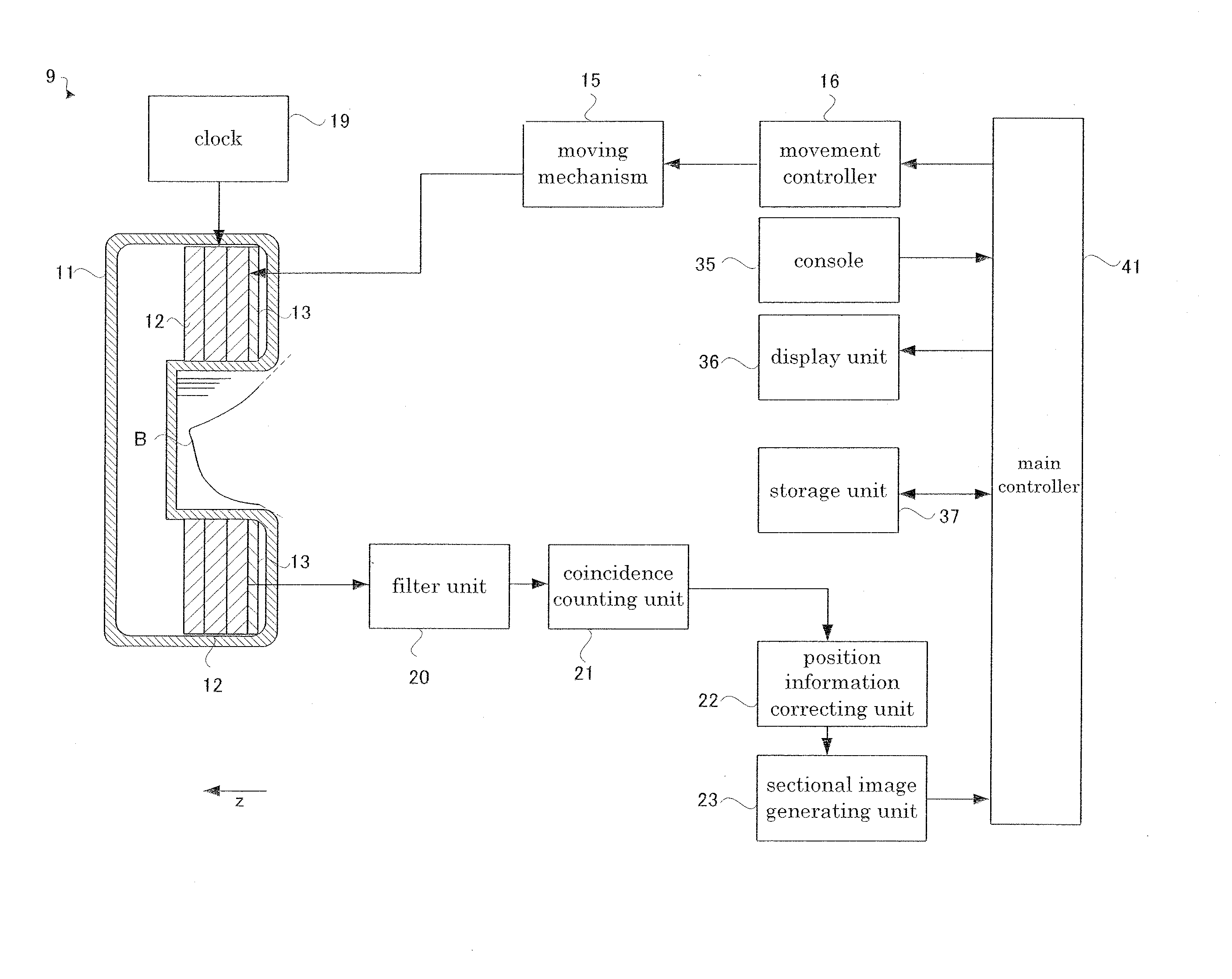
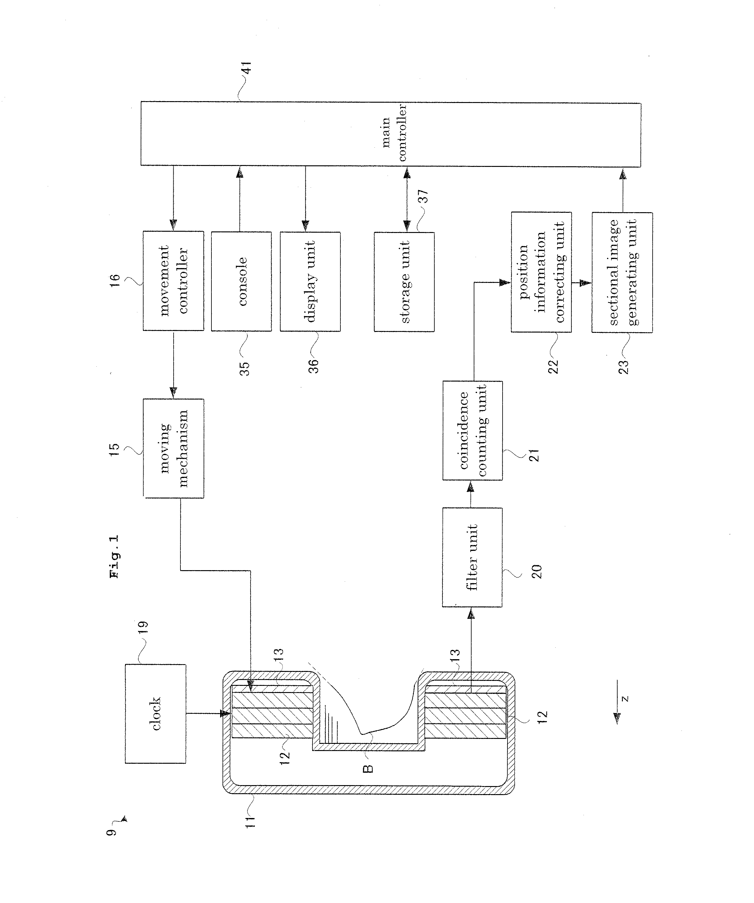
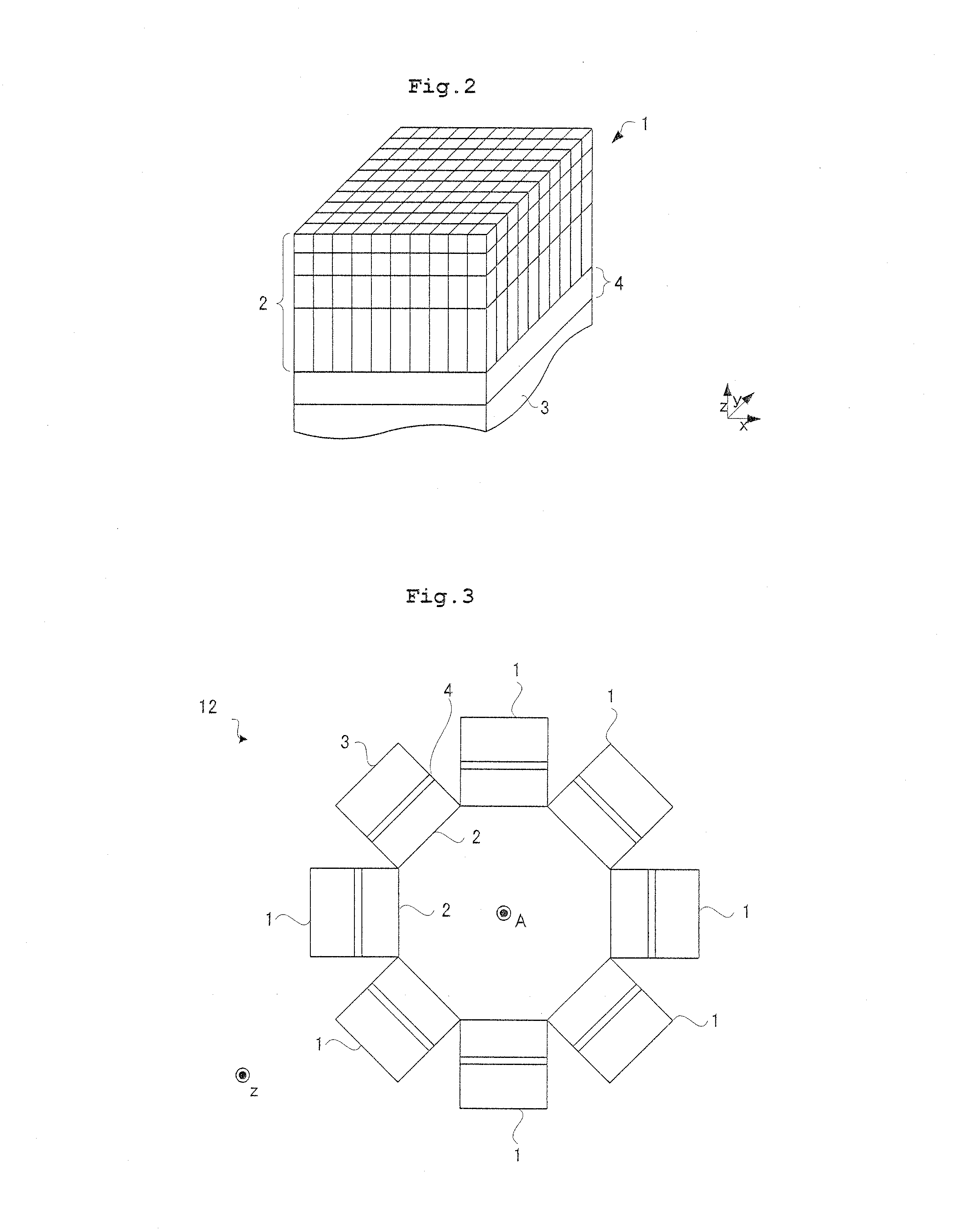
[0037]An embodiment of a sectional radiographic apparatus for breast examination according to this disclosure will be described hereinafter with reference to the drawings. Gamma rays in Embodiment 1 are an example of the radiation in this disclosure. The construction in Embodiment 1 is a mammographic apparatus for breast examination, and description will be made by expressing this as the sectional radiographic apparatus as appropriate. FIG. 1 is a functional block diagram illustrating a specific construction of the sectional radiographic apparatus according to Embodiment 1. The sectional radiographic apparatus 9 according to Embodiment 1 includes a gantry 11 into which a breast of a patient is introduced in z-direction, and a detector ring 12 in an annular shape mounted in the gantry 11 into which the breast of the patient is introduced in the z-direction. The detector ring 12 has an inner hole in a cylindrical shape (shape of an octag...


PUM


Abstract

A sectional radiographic apparatus for breast examination includes a detector ring with radiation detectors arranged arcuately for receiving a breast of a patient, each of the radiation detectors including a scintillator for converting radiation into light, and a photodetector for detecting the light, a moving device for moving the detector ring along a direction of a central axis of the detector ring relative to the breast of the patient, and a movement control device for controlling the moving device.

Description

BACKGROUND OF THE INVENTION[0001](1) Field of the Invention[0002]This invention relates to a sectional radiographic apparatus for breast examination, which detects annihilation radiation pairs emitted from a patient to image a distribution of a radioactive drug in the patient. More particularly, the invention relates to a sectional radiographic apparatus for breast examination, having a detector ring with radiation detectors arranged in a C-shape or in an annular shape (O-shape).[0003](2) Description of the Related Art[0004]Medical equipment includes a sectional radiographic apparatus for imaging a distribution of a radioactive drug. A specific construction of such a sectional radiographic apparatus will be described. As shown in FIG. 9A, a conventional sectional radiographic apparatus has a detector ring 62 with radiation detectors 51 arranged in an annular shape for detecting radiation (see Japanese Unexamined Patent Publication No. 2004-279057). This detector ring 62 detects a ra...

Claims


Application Information

Patent Timeline
Patent Type & Authority Applications(United States)
IPC IPC(8): A61B6/04
CPCA61B6/037A61B6/107A61B6/4258A61B6/502A61B6/4275A61B6/4429A61B6/4266
Inventor TONAMI, HIROMICHI
Owner SHIMADZU CORP
Why Eureka
Try Eureka