

X-ray imaging apparatus
- Summary
- Abstract
- Description
- Claims
- Application Information
AI Technical Summary
Benefits of technology
Problems solved by technology
Method used
Image

Examples
Embodiment Construction
[0035]Various exemplary embodiments, features, and aspects of the invention will be described in detail below with reference to the drawings.
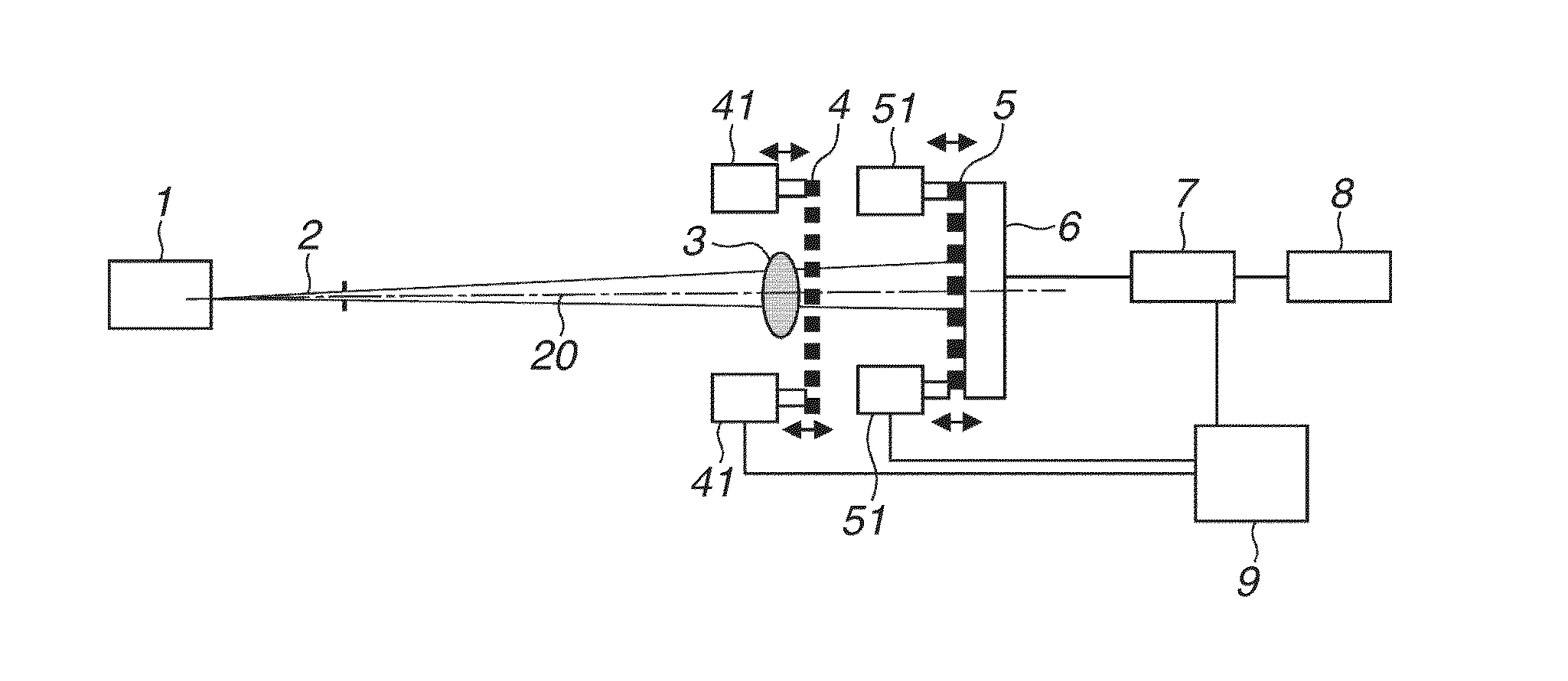
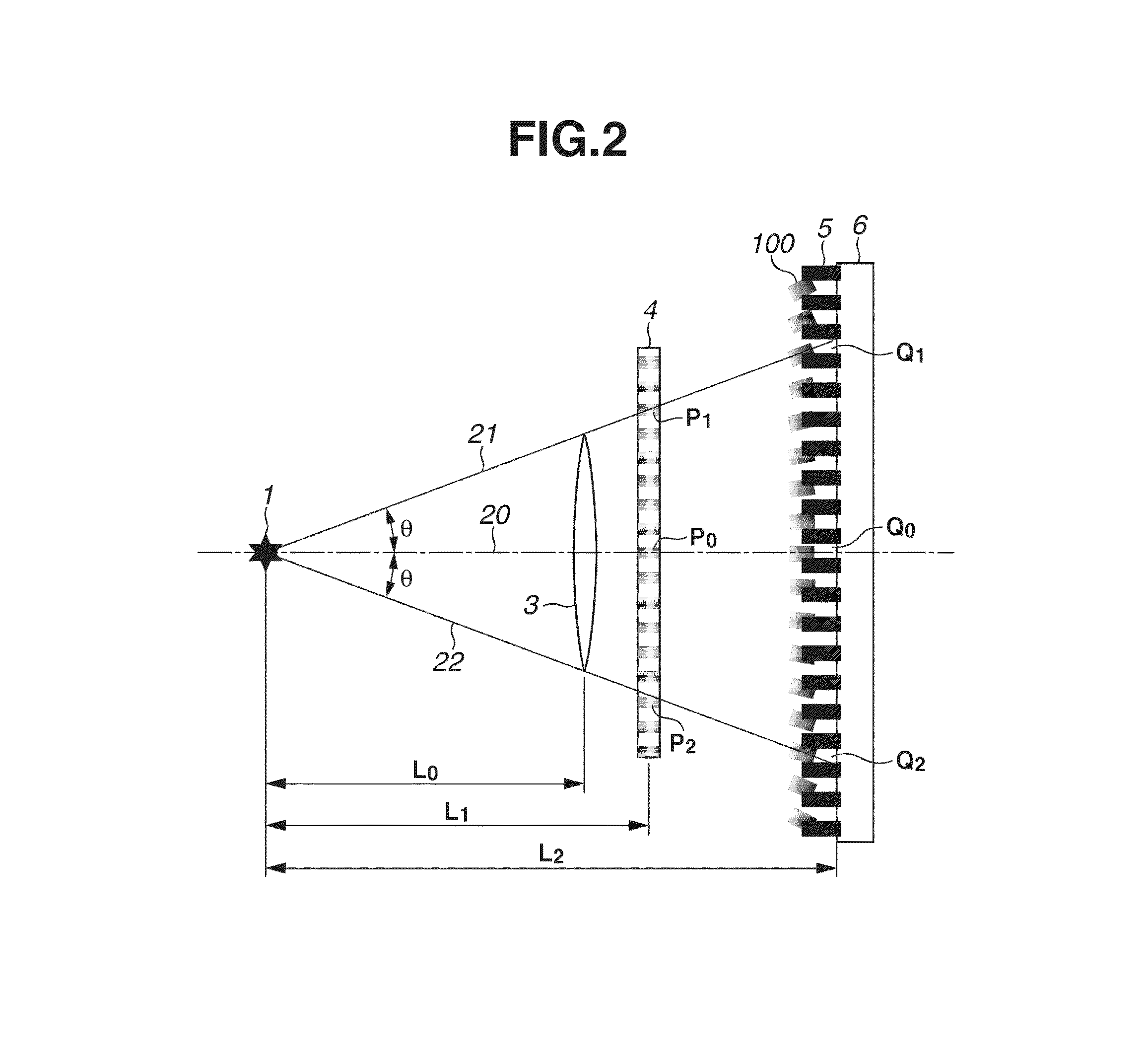
[0036]In each figure, the same reference numerals are assigned to the same members and a repeated description will be omitted. A first exemplary embodiment will be described. In order to achieve the above object, the first exemplary embodiment has the following characteristics. An X-ray imaging apparatus of the present exemplary embodiment includes an X-ray source, a diffraction grating for diffracting an X-ray from the X-ray source to form an interference pattern, a shielding grating for shielding a part of the interference pattern, and a detector for detecting the X-ray passing through the shielding grating. In addition, in the present exemplary embodiment, the shielding grating and the detector are fixed. Further, the X-ray imaging apparatus of the present exemplary embodiment includes an actuator connected to the diffraction grating and an ...
PUM
 Abstract
Description
Claims
Application Information