

Hot isotropic pressure device
- Summary
- Abstract
- Description
- Claims
- Application Information
AI Technical Summary
Benefits of technology
Problems solved by technology
Method used
Image

Examples
first embodiment
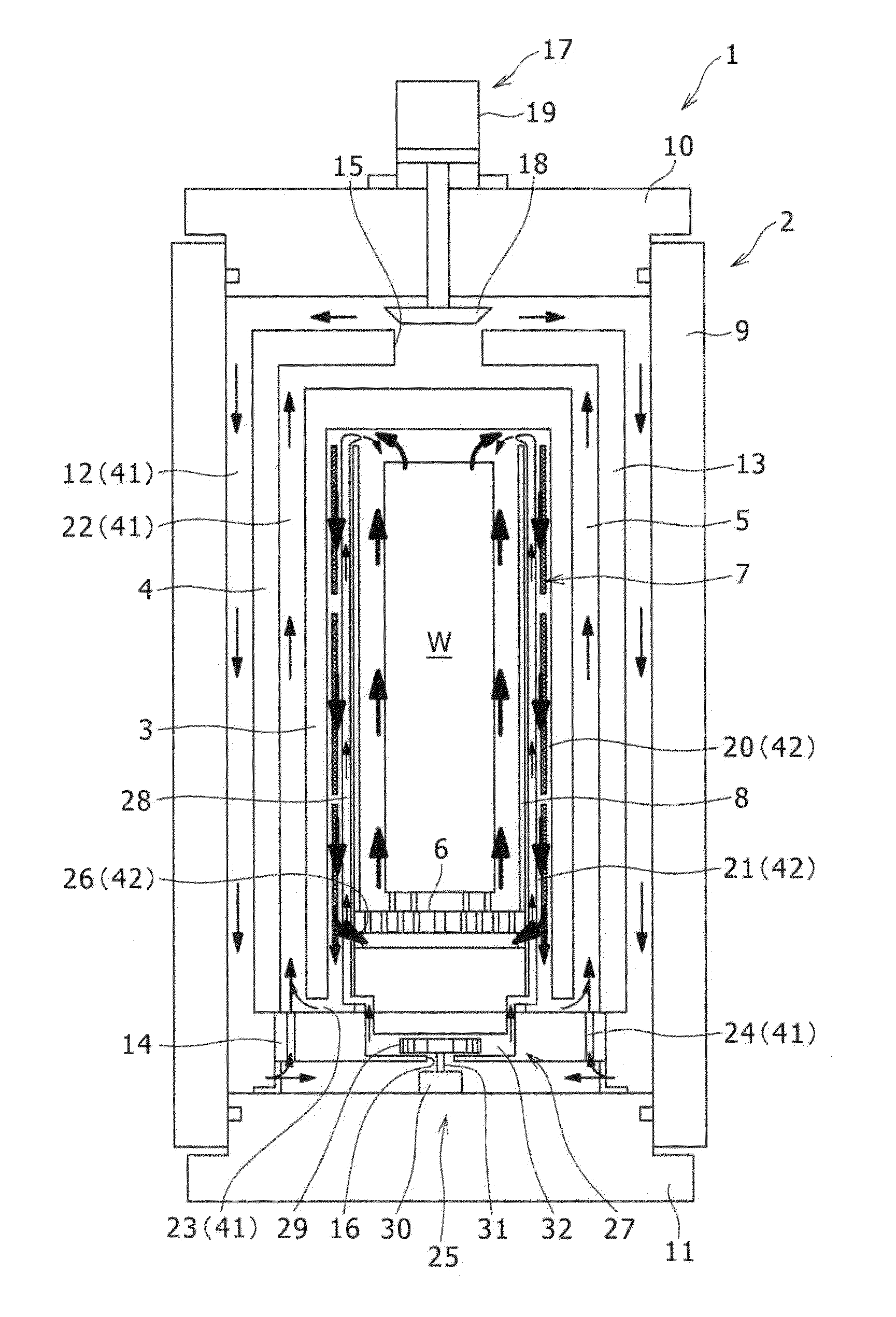
[0037]Hereinafter, a first embodiment of a hot isotropic pressure device according to the invention will be described in detail by referring to the drawings.
[0038]FIG. 1 illustrates a hot isotropic pressure device 1 (hereinafter, referred to as a HIP device 1) of the first embodiment. The HIP device 1 includes a high-pressure container 2 which accommodates a subject treatment material W, and further includes a gas impermeable inner casing 3 and a gas impermeable outer casing 4 which are provided inside the high-pressure container 2, where the gas impermeable inner casing 3 is disposed so as to surround the subject treatment material W, and the gas impermeable outer casing 4 is disposed so as to surround the inner casing 3 from the outside. A heat insulating layer 5 is provided between the inner casing 3 and the outer casing 4, and the inside of the inner casing 3 is adiabatically isolated from the outside by the heat insulating layer 5. In the case of the first embodiment, the inner...
second embodiment
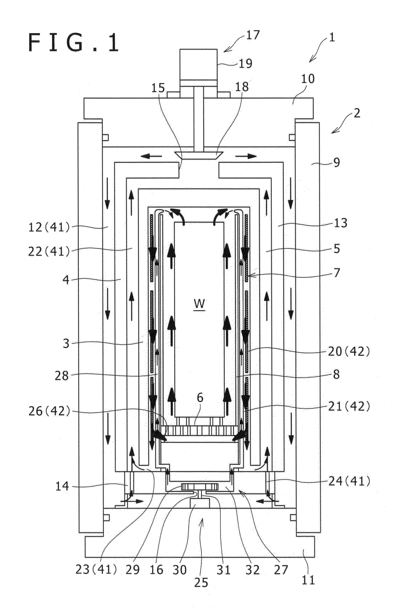
[0082]Next, the HIP device 1 of a second embodiment will be described.
[0083]As illustrated in FIG. 2, as not in the case of the HIP device 1 of the first embodiment, in the HIP device 1 of the second embodiment, a valve unit (a second valve unit 33) is newly provided which adjusts a ratio between the flow rate of the pressure medium gas flowing along the first circulation flow 41 and the flow rate of the pressure medium gas flowing along the second circulation flow 42.
[0084]Specifically, instead of the installation position of the second circulation hole 24, a second valve unit 33 (a throttle valve unit) may be newly provided in the second circulation hole 24. That is, in the HIP device 1 illustrated in FIG. 2, the second circulation hole 24 is opened to both the outer casing bottom body 14 and the fan accommodating portion 32, and a part of the pressure medium gas received in the fan accommodating portion 32 may flow into the inner passageway 22. Then, in the course of the second c...
third embodiment
[0087]Next, the HIP device 1 of a third embodiment will be described.
[0088]As illustrated in FIG. 3, in the HIP device 1 of the third embodiment, only one conduit pipe 28 is provided so as to penetrate the center portion of the rectification cylinder 8 in the vertical direction instead providing plural conduit pipes 28 along the outer peripheral surface or the inner peripheral surface of the rectification cylinder 8. The center portion includes not only the geometric center of the cross section of the rectification cylinder 8, but also the portion deviating from the center by a certain degree, and indicates the center portion excluding the peripheral edge portion of the cross section.
[0089]That is, the fan accommodating portion 32 of the HIP device 1 is divided into two upper and lower chambers, so that the pressure medium gas may flow from a lower fan accommodating portion 32D to an upper fan accommodating portion 32U. Further, one conduit pipe 28 is opened to the center side of th...
PUM
| Property | Measurement | Unit |
|---|---|---|
| Pressure | aaaaa | aaaaa |
| Distance | aaaaa | aaaaa |
Abstract
Description
Claims
Application Information