Mould for moulded parts with internal undercuts

Inactive Publication Date: 2013-03-21
IRUMOLD
View PDF2 Cites 1 Cited by
  • Summary
  • Abstract
  • Description
  • Claims
  • Application Information

AI Technical Summary

Benefits of technology

[0009]Thus, it can be obtained an ensemble of internal core of the mould that fits in a cavity and in which it can be produced moulded parts with internal undercuts corresponding to the intermediate spaces created between the parallel forms of the internal part of the core. This way, thanks to the axial displacement of the internal part of the core, in respect of the external part, together with the moulded part, and to the subsequent turning of the said interna

Problems solved by technology

Similarly, this solution allows the design of parts with steeper undercuts, something which is unviable

Method used


Image

  • Mould for moulded parts with internal undercuts
  • Mould for moulded parts with internal undercuts
  • Mould for moulded parts with internal undercuts

Examples


Embodiment Construction

[0019]The object of the invention is referred to a mould dedicated to the moulding of moulded parts with internal undercuts, offering a simple draft process of the parts without causing distortions.

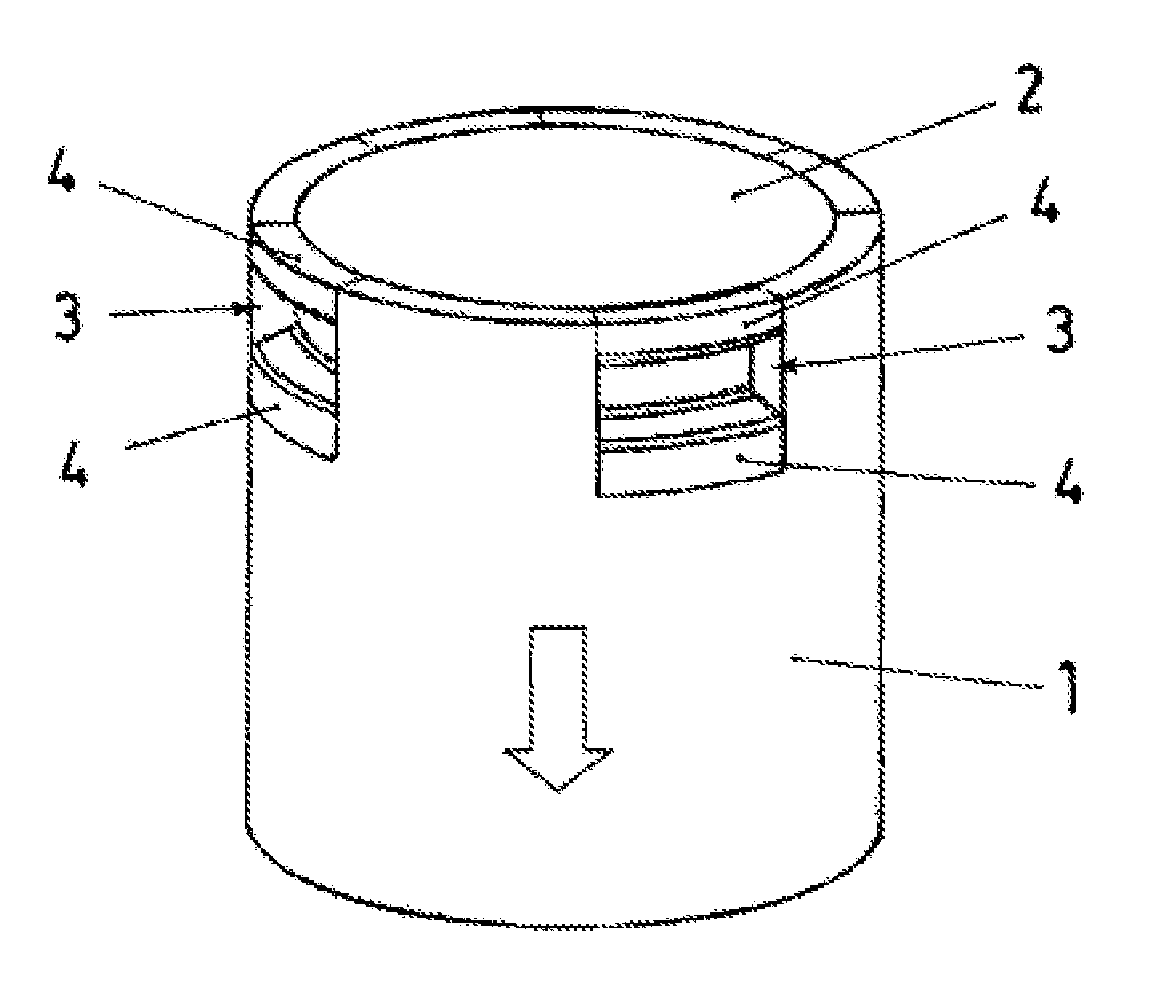
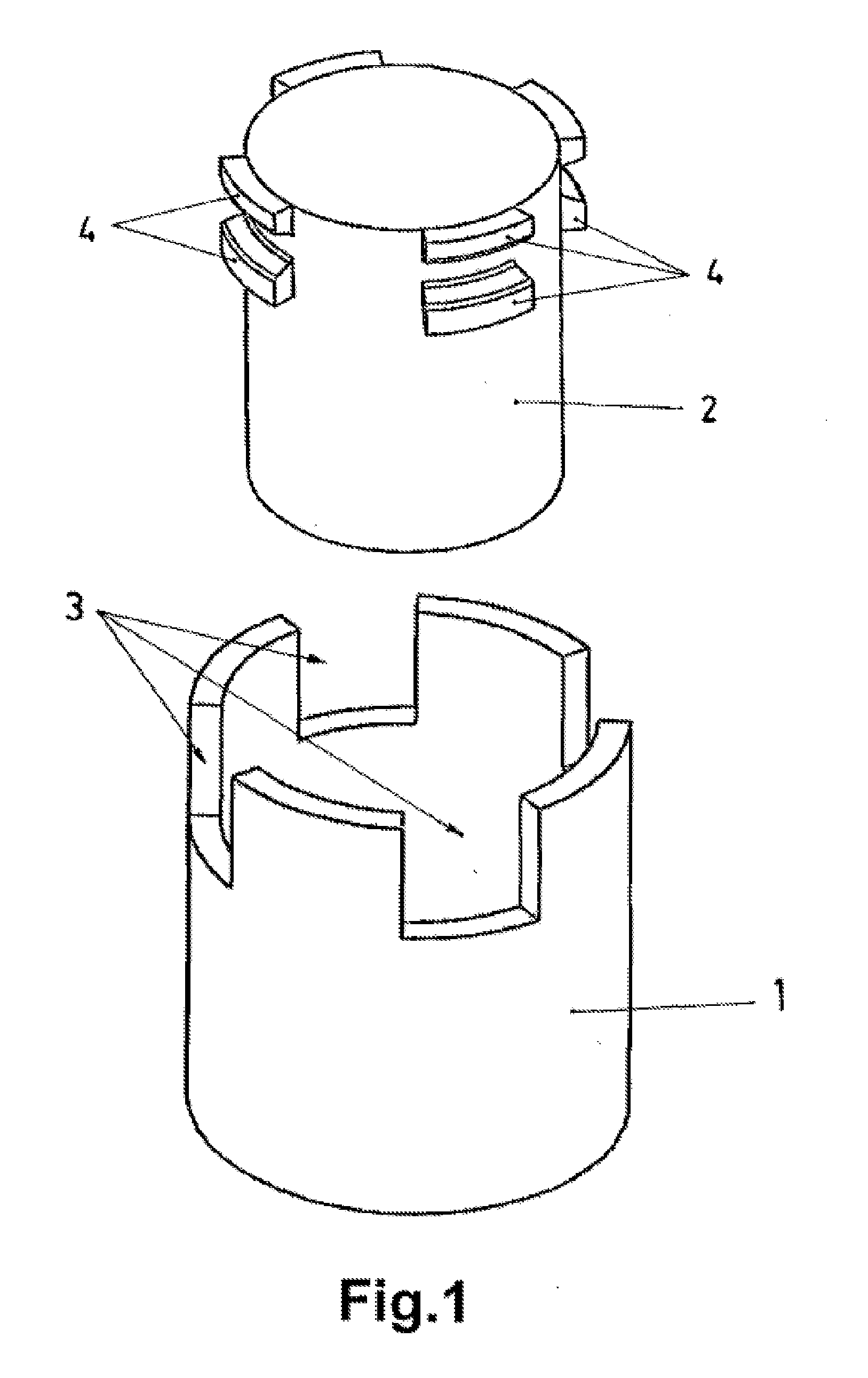
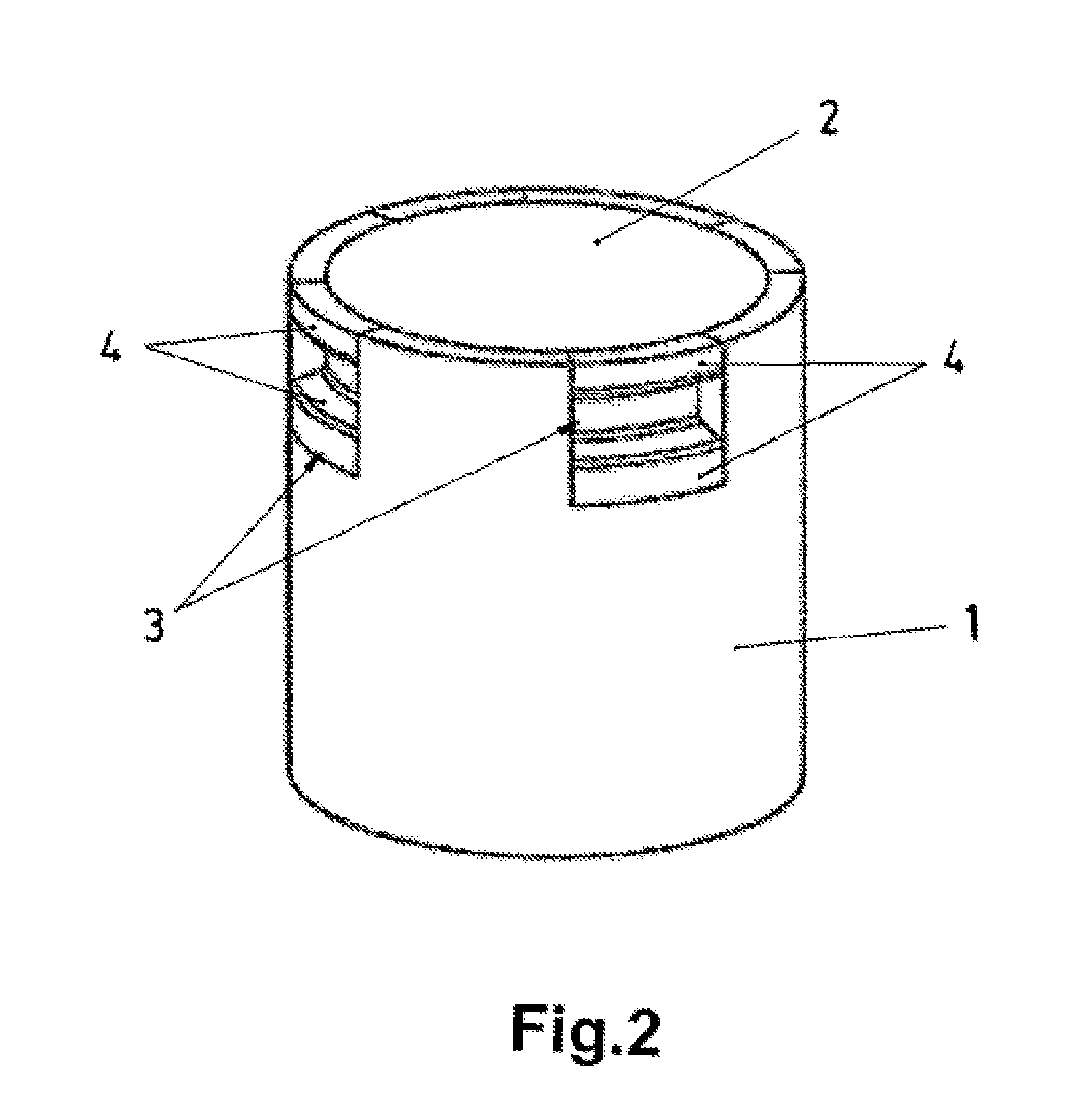
[0020]The recommended mould comprises a core intended to be fitted inside the cavity (not represented) to create a space between both elements where the produced part will be formed. The core is formed by two complementary elements (1 and 2) that fit inside the cavity. The parts are arranged in a linkage situation (one inside the other) being the element part (1) an empty cylinder. Inside this empty cylinder it is inserted the element part (2) which consists of a cylindrical body with a diameter corresponding to the internal diameter of the element part (1).

[0021]The empty cylinder of the element part (1) establishes the edge of the end in which it is inserted the element part (2), various slots (3), while the cylindrical body of the element part (2) has in the peripheral area various par...


PUM

PropertyMeasurementUnit
Fractionaaaaaaaaaa
Diameteraaaaaaaaaa
Displacementaaaaaaaaaa

Abstract

Mould for moulded parts with internal undercuts that comprises a core of the mould with two complementary parts (both fitted one inside the other), providing the possibility of axial displacement and turning among them, establishing the external element part various slots where the parallel forms that the internal element part has in its peripheral area are inserted. Thus, thanks to the axial displacement and the turning of both elements, the parallel forms come out of from the slots and deviate from the coping enabling the ejection of the moulded part without being forced.

Description

FIELD OF THE ART[0001]This invention is related to the obtaining of moulded parts with internal undercuts and it proposes a mould formed by a functional ensemble that enables the draft of this kind of parts without being subject to deteriorating stresses.STATE OF THE ART[0002]Due to the characteristics and possibilities of the technique, the injection moulding is used to produce all kind of parts. Some of these parts have problems during the draft process, and this is significant in the moulded parts with internal undercuts.[0003]To obtain this kind of parts, it is normally used a draft process of forced ejection of the moulded parts. This way, the internal prominent areas of the said parts are subject to distortion stresses that, in case they exceed the yield stress of the material, may cause such deterioration that may lead to the rejection of the parts.[0004]For this purpose, draft methods based on the technique of collapsible cores and mechanical systems of conical or linear dis...

Claims


Application Information

Patent Timeline
IPC IPC(8): B29C45/26
CPCB29C45/4421B29C2045/4492B29C45/2681B29C45/2669B29C45/1705B29C45/4471
Inventor ANTONANA GASTESI, FRANCISCO JAVIERGALE ONECA, FELIXBERRO PREBOSTE, JOSE JAVIERLARUMBE SAN MARTIN, LUIS
Owner IRUMOLD
Why Eureka
Try Eureka