Insulating member for covering a conduit in a clean room

a technology for insulating members and clean rooms, which is applied in the direction of closure stoppers, synthetic resin layered products, packaging, etc., can solve the problems of increasing installation costs, time and complexity, and the bulk of insulating materials can increase costs, and achieves less material to be used, high r-value, and reduced bulk

Inactive Publication Date: 2013-03-21
UFP TECHNOLOGIES
View PDF7 Cites 2 Cited by
  • Summary
  • Abstract
  • Description
  • Claims
  • Application Information

AI Technical Summary

Benefits of technology

[0005]The insulating member of this disclosure, e.g. when utilized in clean room, typically exhibits a high R-value relative to a typical thickness which allows for less material to be used. This not only reduces bulk but also reduces cost. The insulating member also can typically be cut to fit the conduit while in the clean room, e.g. without the use of tents or bags, because the insulating member tends to resist fragmentation and typically produces minimal (if any) dust when cut. This reduces processing complexities, reduces installation time, and reduces overall cost in addition to reducing potential contamination in the clean rooms. Moreover, the insulating member typically can withstand both hot and cold temperatures without failure, resists mold growth, and typically resists degradation and failure when exposed to cleaning and disinfecting products. Furthermore, the insulating member typically produces minimal smoke if burned. This reduces hazards and potential further contamination in case of fire.

Problems solved by technology

The process of insulating clean rooms and the equipment therein (e.g. with insulating members) can be difficult because many traditional insulation materials tend to disintegrate easily and contaminate the clean rooms with dust and particulates.
This increases installation costs, time, and complexity.
In addition, many types of insulation materials are bulky, thereby requiring additional space to be added to clean rooms or causing potential hazards due to lack of space.
In addition, the bulk of these insulation materials increases costs.
Moreover, many types of insulation materials cannot withstand low or high temperatures, temperature fluctuations, or harsh cleaning / disinfecting products that are used to maintain the clean rooms and may support mold growth.

Method used


Image

  • Insulating member for covering a conduit in a clean room
  • Insulating member for covering a conduit in a clean room
  • Insulating member for covering a conduit in a clean room

Examples


Embodiment Construction

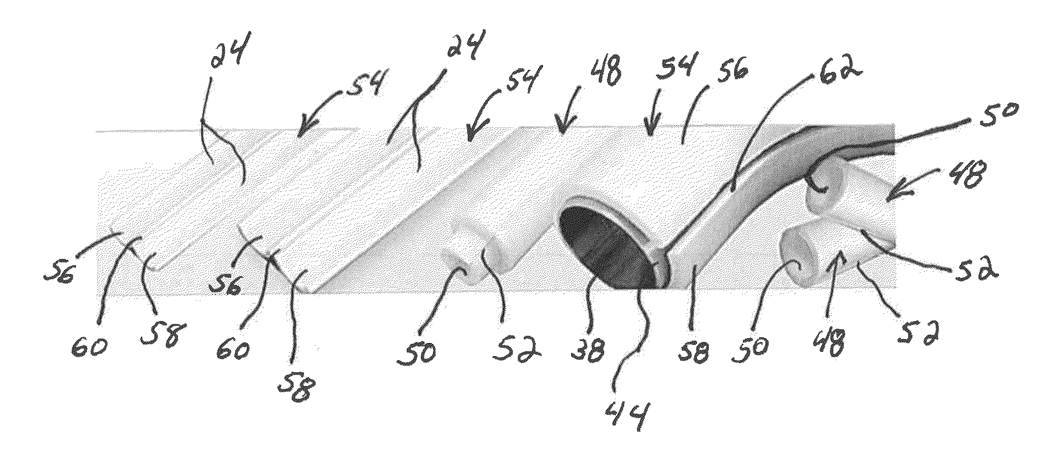
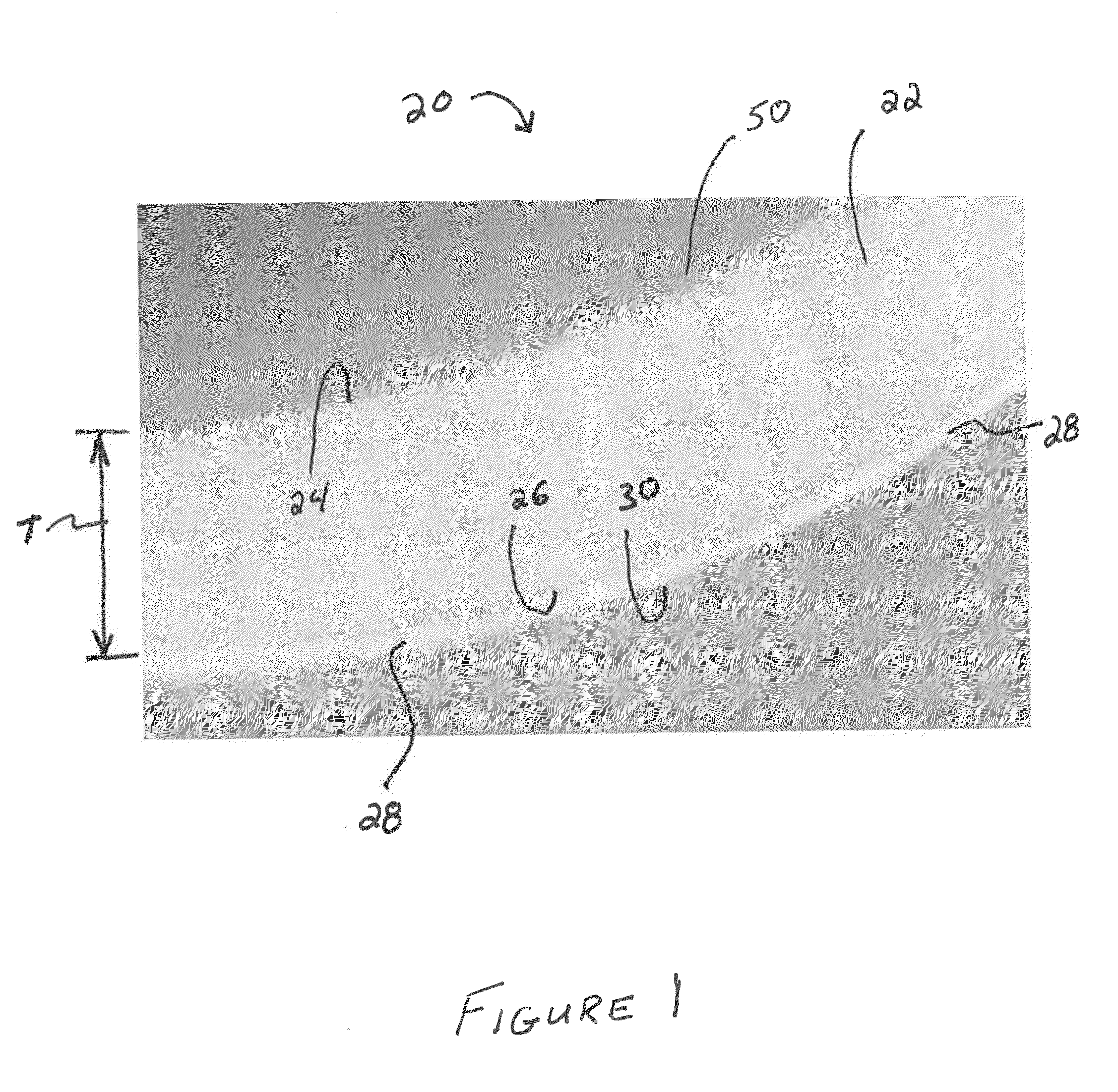
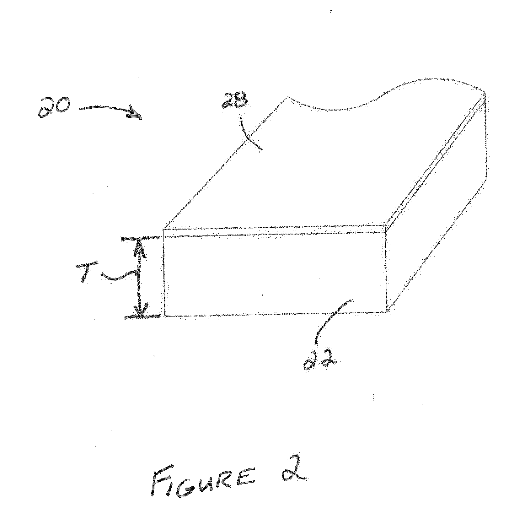
[0020]With reference to the Figures, wherein like numerals indicate like or corresponding parts throughout the several views, an insulating member is generally shown at (20). In one embodiment, the insulating member (20) can be used to partially or completely cover (or be disposed about) all or a portion of a conduit (38), e.g. in FIGS. 5-13. The insulating member (20) may be utilized in clean room or may be utilized for an entirely different purpose or in an entirely different setting. The insulating member (20) is not limited to any particular insulating value or efficiency and may insulate from high and / or low temperatures, e.g. from ambient temperature to about −40° C., from ambient temperature to about 160° C. or, for example, from about 112° F. to about 450° F. All sub-ranges of temperatures within the aforementioned ranges are also hereby expressly contemplated as non-limiting embodiments of this disclosure.

[0021]The terminology “conduit” is not particularly limiting and may ...


PUM

PropertyMeasurementUnit
thicknessaaaaaaaaaa
thicknessaaaaaaaaaa
temperaturesaaaaaaaaaa

Abstract

This disclosure provides an insulating member for covering a conduit in a clean room. The insulating member typically has a length and defines a cavity extending along the length. The cavity is sized and shaped to receive the conduit. The insulating member typically includes an innermost layer that may be a closed cell fluoropolymer foam and is disposed to contact the conduit. The insulating member also typically includes an outermost layer that is disposed on the innermost layer and that may be a second fluoropolymer.

Description

CROSS-REFERENCE TO RELATED APPLICATIONS[0001]The subject patent application claims priority to and all the benefits of U.S. Provisional Patent Application Nos. 61 / 535,914 filed on Sep. 16, 2011, and 61 / 647,216 filed on May 15, 2012, each of which is expressly incorporated herein by reference in its entirety.FIELD OF THE DISCLOSURE[0002]The subject disclosure generally relates to an insulating member for covering a conduit in a clean room. More specifically, the subject disclosure relates to an insulating member that typically includes a fluoropolymer foam.BACKGROUND OF THE DISCLOSURE[0003]Clean rooms are controlled environments in which air quality is closely monitored for particle content. Many clean rooms include equipment, such as pipes, that are chilled or heated. The process of insulating clean rooms and the equipment therein (e.g. with insulating members) can be difficult because many traditional insulation materials tend to disintegrate easily and contaminate the clean rooms ...

Claims


Application Information

Patent Timeline
Patent Type & Authority Applications(United States)
IPC IPC(8): B32B27/06B32B27/08F16L59/02
CPCF16L59/023Y10T428/1376F16L59/163F16L59/22B32B5/18B32B7/12B32B27/065B32B27/304B32B27/32B32B27/34B32B1/08B32B2266/0235B32B2266/08B32B2307/304B32B2307/4026B32B2597/00C08J9/365C08J2205/052C08J2327/16C08J2423/06C08J2423/12C08J2477/02F16L59/029
Inventor MACNEILL, RONALDSAVA, TUNAKING, MICHAEL JOSEPH
Owner UFP TECHNOLOGIES
Why Eureka
Try Eureka