
Solid freeform fabrication using a plurality of modeling materials

a technology of modeling materials and solids, applied in the direction of additive manufacturing processes, manufacturing tools, instruments, etc., can solve the problems of insufficient material limited number of building materials that can be used or produced in conventional techniques, and inability to achieve the properties of standard engineering polymers, so as to achieve easy burn

Active Publication Date: 2013-03-21
STRATASYS LTD
View PDF15 Cites 132 Cited by
  • Summary
  • Abstract
  • Description
  • Claims
  • Application Information

AI Technical Summary

Benefits of technology

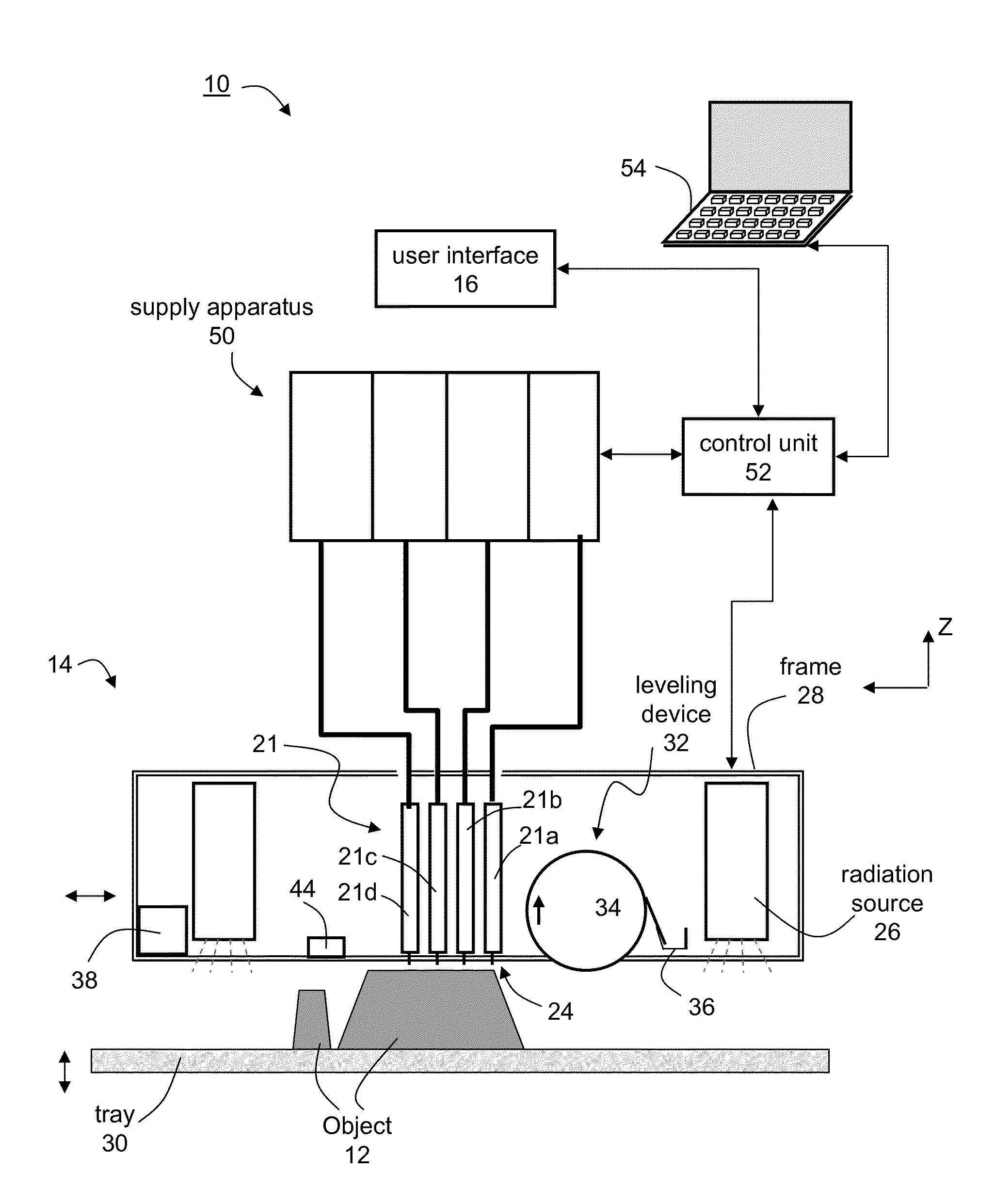
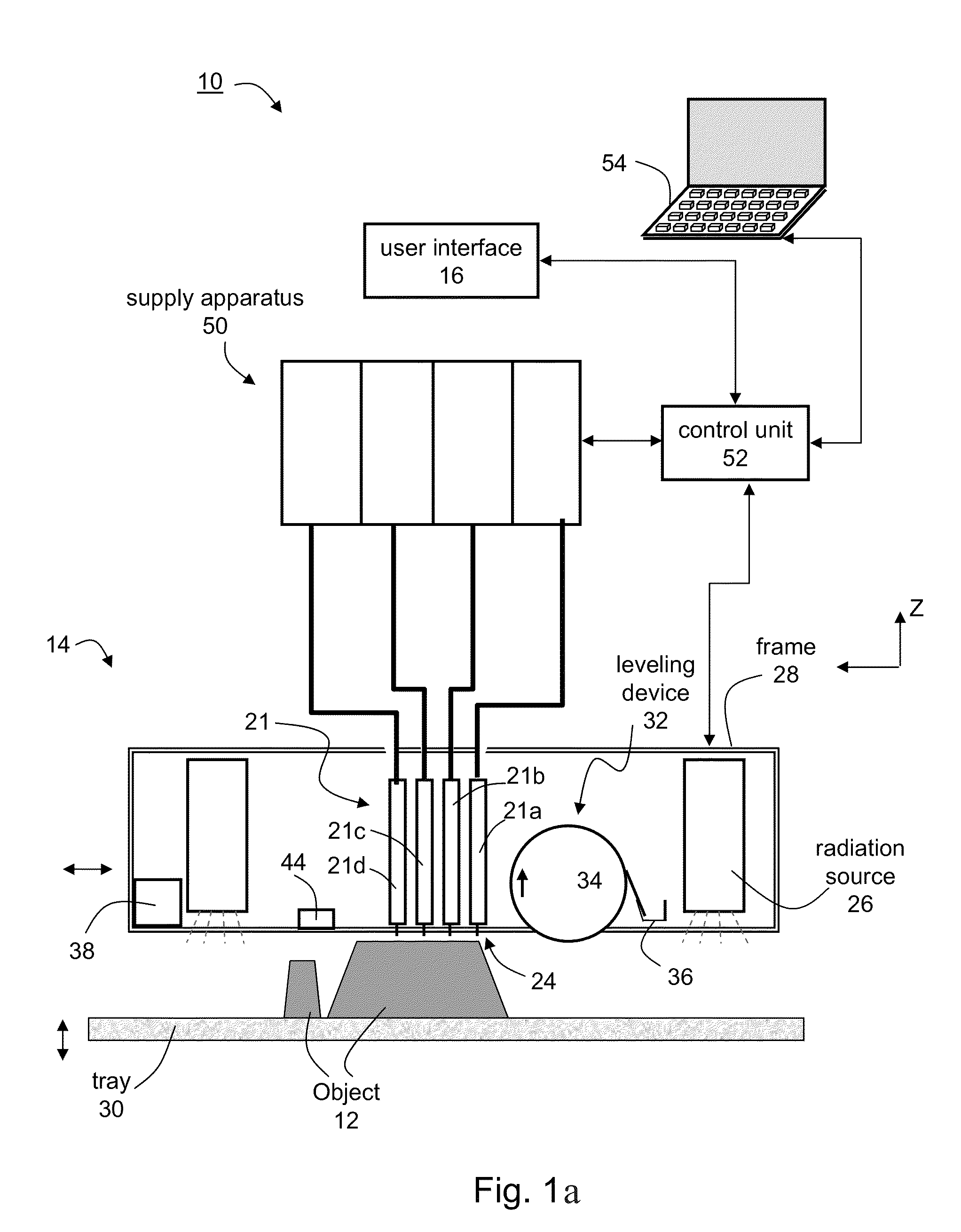
[0033]The ability of the system of the present embodiments to utilize two or more different modeling materials, makes it is possible to use and / or produce many more, and more varied materials in solid freeform fabrication than has been possible to date in conventional solid freeform fabrication techniques, as well as providing many different possibilities for combining multiple materials, according to the final object and / or object properties desired to be obtained.
[0034]The ability of the system of the present embodiments to utilize two or more different modeling materials, allows the fabrication of parts or objects having properties which are difficult, if not impossible, to achieve using conventional solid freeform fabrication techniques. For example, modeling materials which have a great tendency to shrink as a result of the polymerization process are not usually suitable for use in traditional solid freeform fabrication apparatus. A modeling material suffering from high shrinkage during solidification makes especially difficult the manufacturing of bulky three dimensional geometries but may allow the fabrication of thin shell like three dimensional geometries, for example, around a bulky object which is fabricated of a material with acceptable shrinkage. The system of the present embodiments usefully provides a solution to this problem. For example, the system of the present embodiments can fabricate parts or objects in which the surfaces of the part or object are made of one material, while the internal regions of the part or object comprise a different material. In this example, the internal regions may be fabricated of a material which lacks mechanical strength, such as a gel or liquid, but having other desirable properties such as being easily burnt without leaving ash or other traces.
[0035]The ability of the system of the present embodiments to utilize two or more different modeling materials, also allows the fabrication of objects via a segmentation process, wherein layers are built in segments or “tiles”. Such process is described in U.S. Application No. 60 / 430,362 and U.S. Pat. No. 7,300,619, the contents of which are hereby incorporated by reference. The segments or tiles may be comprised of one material, and joined by dispensing a different material, e.g., a binder or glue-like material, in the breaks between the segments. By building in smaller segments or tiles instead of a full layer, this method serves to overcome problems of material shrinkage which may occur during the curing process.
[0069]According to some embodiments of the present invention the control unit is designed and constructed to ensure that the object's dimensions are rescaled along at least one direction so as to compensate for post-formation shrinkage of the object along the at least one direction.

Problems solved by technology

The present inventors also found that the number of building materials that can be used or produced in conventional techniques is very limited, and the properties of the materials that can be obtained are still far inferior compared to the properties of standard engineering polymers.

Method used


Image

  • Solid freeform fabrication using a plurality of modeling materials
  • Solid freeform fabrication using a plurality of modeling materials
  • Solid freeform fabrication using a plurality of modeling materials

Examples


example 1

System Operation Protocols

[0272]In the present Example, an object is defined as a volume in space (usually specified in an X, Y, Z coordinate system) which is confined by one or more close surfaces which do not intersect with each other (see, e.g., FIG. 2a). A region in the object is a sub-volume of the object which is confined in one or more close surfaces which do not intersect with each other (see, e.g., FIG. 2b).

[0273]A communication file is a file in which the specification of an object is saved by the CAD Software and from which the solid freeform fabrication apparatus retrieves the full information on the object. The structure and format of the communication file is known to both the CAD and the software controlling the solid freeform fabrication apparatus.

[0274]An STL file is an example of communication files that both CAD and the software controlling the solid freeform fabrication apparatus recognize. In an STL file, the object is specified by a series of triangles that opt...

example 2

Exemplified Workflow

[0284]The present Example describes a workflow for building one or more three-dimensional objects from several materials, according to some embodiments of the to present invention. The workflow includes several stages which can be executed by the user or automatically.

[0285]The solid freeform fabrication apparatus is fed by different input materials, each being fed into a different container. In the following, N represents the number of different input materials. It is noted that the number of occupied containers in the solid freeform fabrication apparatus can be more than N, in which case two or more containers include the same material.

[0286]A computer, which is capable of communicating with the solid freeform fabrication apparatus, receives a list of groups of input materials which are allowed to be fed together into the apparatus. Each group can comprise from 2 to N combinable input materials. Materials which are not allowed to combine are not included in the...

example 3

Software Application for Combining 2 Materials in an Object

[0293]The background art fails to teach how different building materials can be used in order to build complex object assemblies and how a communication file representing a three dimensional object can be manipulated in order to build a three dimensional object comprising more than one material.

[0294]The following example describes a method suitable for designing and building an object from a composite material. The method enables the definition of composite material structures, without the need for standard CAD software in order to design the full three-dimensional structure, thus saving on the time that would be required for the design process as well as saving computer memory resources which would usually be required in order to design three-dimensional structures and for the analysis of such three-dimensional structure during the building process.

General

[0295]The method comprises Boolean comparison between bitmaps repres...


PUM

PropertyMeasurementUnit
widthaaaaaaaaaa
thicknessaaaaaaaaaa
thicknessesaaaaaaaaaa

Abstract

A system and methods for solid freeform fabrication of an object is disclosed. The system comprises a solid freeform fabrication apparatus having a plurality of dispensing heads, a building material supply apparatus configured to supply a plurality of building materials to the fabrication apparatus, and a control unit configured for controlling the fabrication apparatus and the supply apparatus based on an operation mode selected from a plurality of predetermined operation modes.

Description

RELATED APPLICATIONS[0001]This application is a continuation of U.S. patent application Ser. No. 12 / 692,695 to filed on Jan. 25, 2010, which is a continuation of PCT Patent Application No. PCT / IL2008 / 001025 having International Filing Date of Jul. 24, 2008, which claims the benefit of priority of U.S. Provisional Patent Application No. 60 / 935,090 filed on Jul. 25, 2007. The contents of the above applications are all incorporated herein by reference.FIELD AND BACKGROUND OF THE INVENTION[0002]The present invention relates to solid freeform fabrication and, more particularly, to a solid freeform fabrication using a plurality of modeling materials.[0003]Solid Freeform Fabrication (SFF) is a technology enabling fabrication of arbitrarily shaped structures directly from computer data via additive formation steps.[0004]The basic operation of any SFF system consists of slicing a three-dimensional computer model into thin cross sections, translating the result into two-dimensional position d...

Claims


Application Information

Patent Timeline
Patent Type & Authority Applications(United States)
IPC IPC(8): G06T17/00
CPCB29C67/0059B29C67/0092G06T17/00B29K2105/0058B29K2105/24B33Y10/00B33Y30/00B33Y50/02B33Y80/00B29C64/106B29C64/112B29C64/20B29C64/393B29C64/40Y10T428/24802B29C67/202B29C64/268
Inventor NAPADENSKY, EDUARDO
Owner STRATASYS LTD
Learn More