Method and device for detection of contamination by fuel of the oil circuit of a turbine

a technology of oil circuit and turbine, which is applied in the direction of machines/engines, analogue processes for specific applications, instruments, etc., can solve the problems of circuits and abnormally low oil level, and achieve the effect of reducing the weight of the equipment concerned and avoiding these disadvantages

Inactive Publication Date: 2013-03-21
SN DETUDE & DE CONSTR DE MOTEURS DAVIATION S N E C M A
View PDF4 Cites 10 Cited by
  • Summary
  • Abstract
  • Description
  • Claims
  • Application Information

AI Technical Summary

Benefits of technology

[0007]The objective of the present invention is to eliminate these disadvantages by proposing a method and a device for protection against the risks associated with contamination by fuel of the oil circuit of a turbomachine, which assures continual monitoring and makes possible a reduction of weight for the equipment concerned.
[0012]These two alternative solutions make it possible to implement the method throughout the duration of the flight of the aircraft, and not to limit the duration solely to the phases of stabilized cruising.
[0013]According to a preferred embodiment, the set decrease is replaced by a positive or zero increase in any interval of time. This solution makes it possible to simplify the method, by taking into account only an increase in the volume of oil in the tank, and not taking into account the time which has elapsed during the monitoring.
[0015]Preferably, the computer additionally comprises an input which can receive data relating to the engine speed of said turbomachine, and it inhibits the triggering of the alert if a deceleration of the engine speed of the turbomachine takes place during said interval of time.
[0017]In a simplified version, the computer comprises an input which can receive data relating to the start and end of cruising of an aircraft on which said turbomachine is installed, and it inhibits the triggering of the alert outside said cruising phase.

Problems solved by technology

Apart from during deceleration of the engine or an increase in its temperature, the detection of an increase, or an abnormally low decrease in the level of oil in the tank indicates that contamination of the oil circuit has taken place, and that a fluid, probably fuel, has penetrated into this circuit.

Method used


Image

  • Method and device for detection of contamination by fuel of the oil circuit of a turbine
  • Method and device for detection of contamination by fuel of the oil circuit of a turbine
  • Method and device for detection of contamination by fuel of the oil circuit of a turbine

Examples


Embodiment Construction

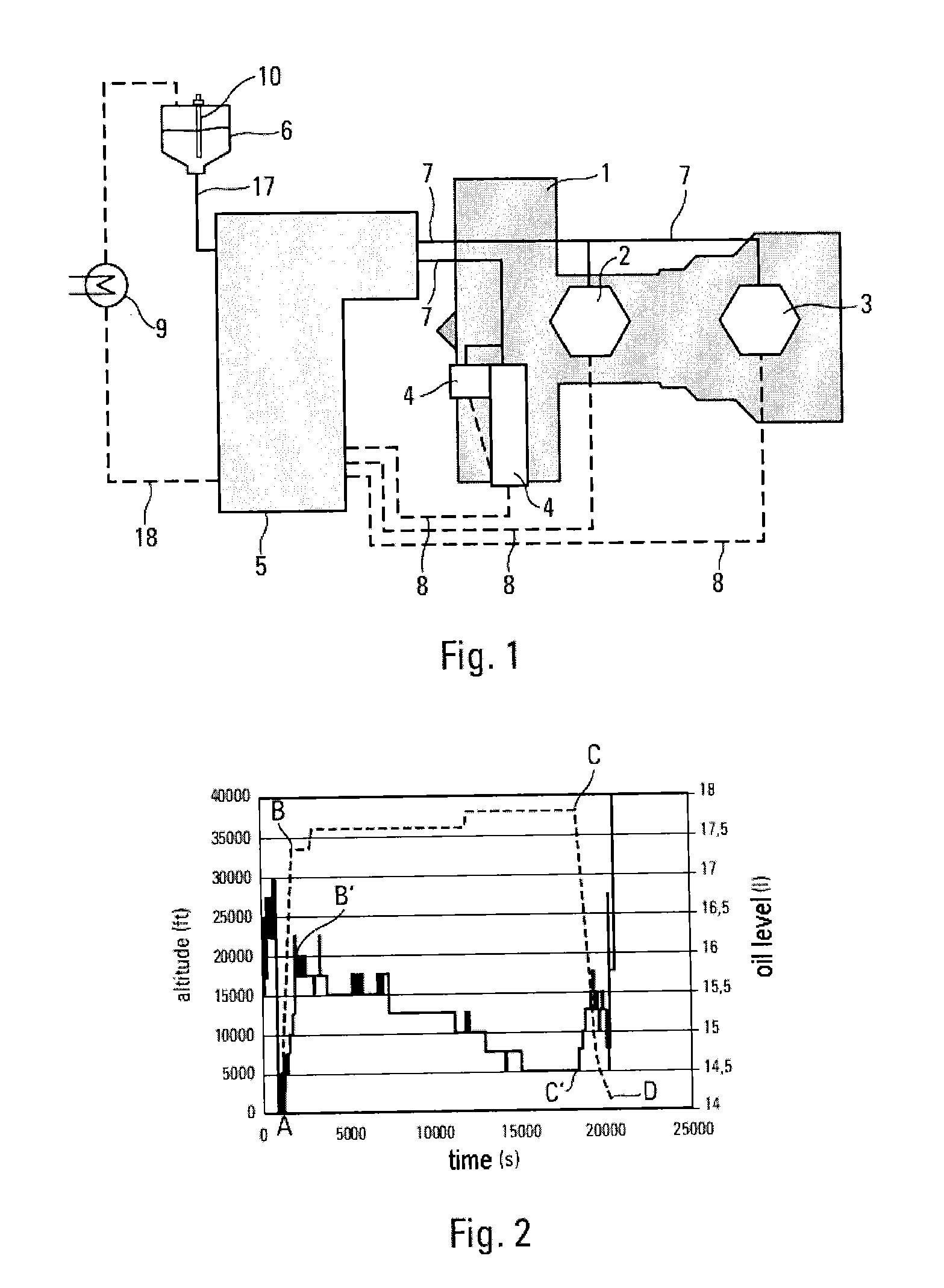
[0024]FIG. 1 shows the lubrication circuit of the chambers and gearboxes of a turbomachine 1. The latter comprises two chambers, i.e. an upstream chamber 2 and a downstream chamber 3, which contain bearings and gears associated with the rotation shafts of the turbomachine. It also comprises gearboxes 4 (two of which are represented), which are used in order to assure driving of the accessories by the turbomachine. In order to assure the lubrication of these chambers and gearboxes, the turbomachine bears a lubrication unit 5, which, by means of pumps and valves, assures the control of the circulation of the oil between the main oil tank 6 and the different units, by means of supply piping 7 and recuperation piping 8. The unit 5 collects oil from the tank 6 via feeding piping 17, and conveys it via the supply piping 7 to the different units. The oil is recuperated in the low part of these chambers and accessory housings by the recuperation piping 8, which supplies it to the lubricatio...


PUM


Abstract

A method for detection of contamination, by another fluid, of the oil circuit of a turbomachine fitted on an aircraft, the oil circuit including a tank provided with a device for measuring its oil level, piping which connects the tank to the various units of the turbomachine to be lubricated, and a device for putting the oil into circulation between the tank and the units, the turbomachine including a device for measuring its engine speed and a device for measuring the temperature of the oil at one point at least of the oil circuit. The oil level in the tank is monitored, an alert is triggered if the decrease in the oil level, measured over a given interval of time, becomes lower than a set minimum decrease. The decrease can be replaced by a simple increase in the oil level, without taking a duration of the monitoring into account.

Description

BACKGROUND OF THE INVENTION[0001]The field of the present invention is that of turbomachines, and more particularly that of lubrication of these turbomachines.[0002]From upstream towards downstream in the direction of the flow of the gases, a turbomachine for an aircraft generally comprises a fan, one or a plurality of compressor stages, for example a low-pressure compressor and a high-pressure compressor, a combustion chamber, one or a plurality of turbine stages, for example a high-pressure turbine and a low-pressure turbine, and a gas exhaust pipe. A turbine can correspond to each compressor, the two being connected by means of a shaft, thus forming for example a high-pressure core and a low-pressure core. The turbomachine generally has firstly, substantially at the level of the upstream end of the high-pressure core, an “upstream chamber”, and secondly, substantially at the level of the downstream end of the high-pressure core, a “downstream chamber”, these two chambers containi...

Claims


Application Information

Patent Timeline
Patent Type & Authority Applications(United States)
IPC IPC(8): B64D45/00
CPCF01M11/12F16N2250/08F16N2250/16Y02T50/671F01D25/18F05D2260/80F05D2260/609Y02T50/60
Inventor MULLER, JEAN-LOUISDEMAISON, FRANCOISPOTEL, NICOLAS
Owner SN DETUDE & DE CONSTR DE MOTEURS DAVIATION S N E C M A
Why Eureka
Try Eureka