
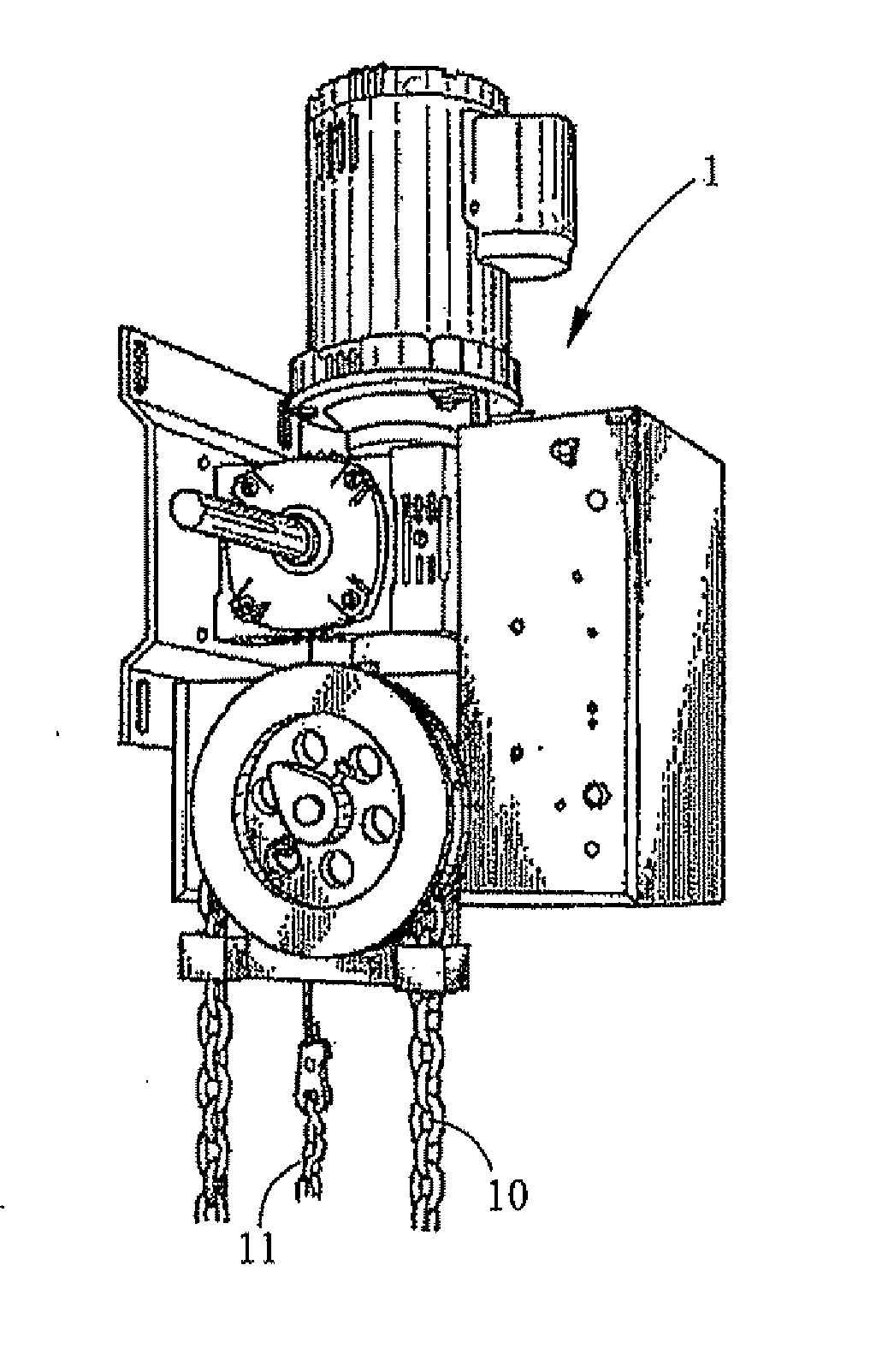
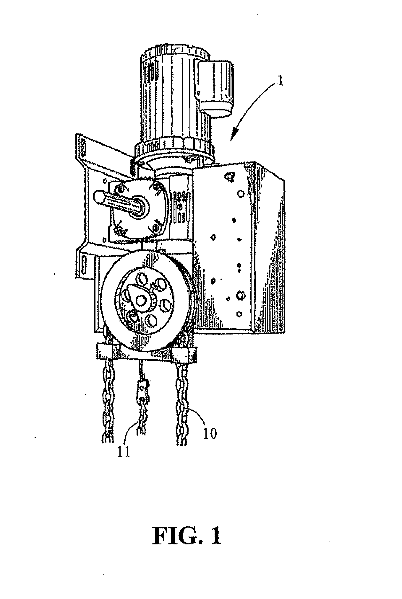
Door machine having chain disk locking mechanism

a technology of locking mechanism and chain disk, which is applied in the direction of door/window protective devices, door/window fittings, constructions, etc., can solve the problems of shortening the life of the locking mechanism, high chance of failure, and complex structure of the clutch mechanism, so as to reduce the cost, simplify the mechanical components, and extend the service life

Active Publication Date: 2013-03-28
HSIEH CHUNG HSIEN
View PDF4 Cites 13 Cited by
  • Summary
  • Abstract
  • Description
  • Claims
  • Application Information

AI Technical Summary

Benefits of technology

The present invention provides an electric door machine with a chain disk locking mechanism that reduces costs by eliminating the need for a clutch mechanism. The machine has simplified mechanical components and is easy to assemble and maintain. The chain disk locking mechanism allows for adjustment of brake force by adding or removing brake disks and brake wheels according to practical demand. The machine also includes an electromagnetic brake module that achieves double braking effect and an elastic element that forces the brake disk to press against the end disk to effect braking. The invention provides flexibility in the quantity of brake components to adjust brake force.

Problems solved by technology

Frequent opening / shutting may cause shorter lifetime of the rolling door.
However, the clutch mechanism is complicated in structure and very expensive, what is more, the chances of failure are high.

Method used


Image

  • Door machine having chain disk locking mechanism
  • Door machine having chain disk locking mechanism
  • Door machine having chain disk locking mechanism

Examples


Embodiment Construction

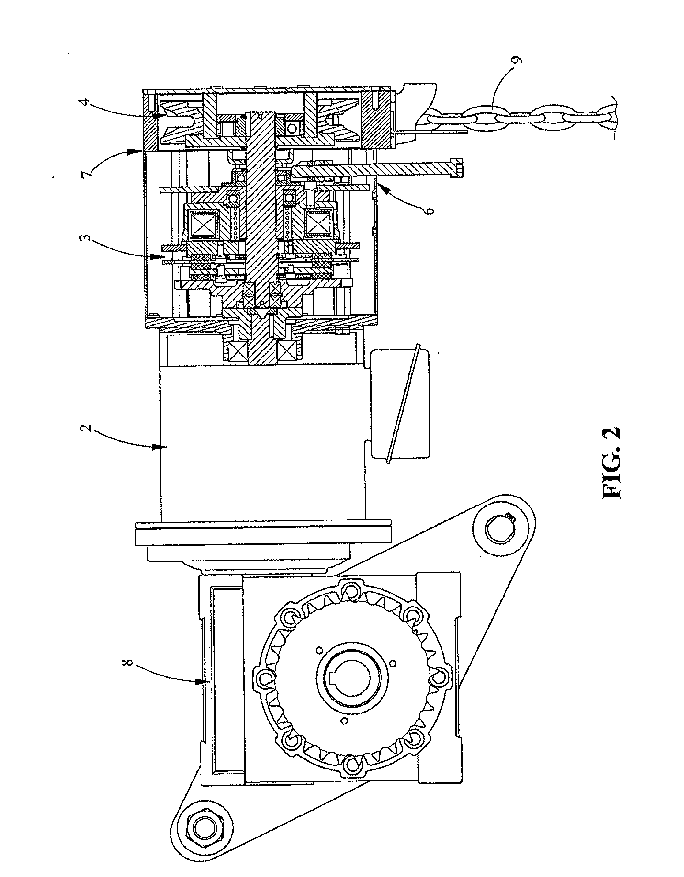
[0027]FIG. 2 is a schematic view showing a preferred embodiment of the electric door machine of the present invention. As shown in FIG. 2, the electric door machine comprises an electric motor 2, an electromagnetic brake module 3, a chain disk locking mechanism 4, a brake release mechanism 6, an outer casing 7, and a reduction mechanism 8. The electromagnetic brake module 3, the chain disk locking mechanism 4, and the brake release mechanism 6 are accommodated in the outer casing 7. The outer casing 7 enclosing the aforementioned mechanisms is connected at one side of the electric motor 2, and the reduction mechanism 8 connected at the other side. The reduction mechanism 8 may reduce the output speed of the electric motor 2 for moving the rolling door (not shown). In other words, the reduction mechanism 8 is designed to control the upward / downward rolling speed of the rolling door. The degree of reduction provided by the reduction mechanism 8 can be adjusted according to practical d...


PUM


Abstract

A door machine having an electric motor and a chain disk locking mechanism. The chain disk locking mechanism includes a chain disk, an engaging rotary block, a stationary shaft and a plurality of moving pins. When the chain disk is pulled to rotate, the fixed pins of the chain disk press the moving pins so as to push the engaging rotary block to rotate with the stationary shaft together. When the stationary shaft is pulled to rotate, the engaging rotary block prohibits the moving pins from rotation. When the chain disk is pulled manually, the rolling door can be rolled upward or downward; when cease pulling the chain disk, braking is immediately effected so as to prevent the rolling door from moving upward or downward. Hence, the clutch mechanism can be omitted for cost saving and the structure of the mechanism can be simplified.

Description

BACKGROUND OF THE INVENTION[0001]1. Field of the Invention[0002]This invention relates to a door machine having a chain disk locking mechanism, more particularly to an electric rolling door having a feature of opening / shutting in high speed, which is suitable for warehouse or garage needing frequent opening / shutting.[0003]2. Description of the Related Art[0004]Accompanying with the rising of Environment Protection and energy saving consciousness, for example, of avoiding cold air or warm air from leaking to outside, the opening / shutting of electric rolling door used for ordinary warehouse or garage becomes very frequent. Frequent opening / shutting may cause shorter lifetime of the rolling door. Further, in order to prevent cold / warm air from leaking to outside, there is a demand to increase the running speed of the electric rolling door.[0005]Conventional electric door machine has a clutch which switches between the motor driven rolling and manual chain disk rolling. However, the clu...

Claims


Application Information

Patent Timeline
IPC IPC(8): E05F15/10
CPCE05Y2800/11E05Y2900/146E05F15/684E06B2009/807E05Y2900/106E06B9/80E05Y2900/00E05Y2400/3013
Inventor HSIEH, CHUNG HSIEN
Owner HSIEH CHUNG HSIEN
Learn More