High-strength pintles and anchoring systems utilizing the same

a high-strength pintle and anchoring system technology, applied in the direction of building reinforcements, construction, building components, etc., can solve the problems of low veneer strength of anchoring systems, and failure of anchoring systems, etc., to achieve high-strength installations that are easy to manufacture, reduce the effect of labor intensity

Active Publication Date: 2013-03-28
HOHMANN & BARNARD INC
View PDF2 Cites 32 Cited by
  • Summary
  • Abstract
  • Description
  • Claims
  • Application Information

AI Technical Summary

Benefits of technology

[0031]It is another object of the present invention to provide labor-saving devices to simplify seismic and nonseismic high-strength installations of brick and stone veneer and the securement thereof to an inner wythe.
[0032]It is yet another object of the present invention to provide a cold worked wire formative that is characterized by high resistance to compressive and tensile forces.
[0033]It is a further object of the present invention to provide an anchoring system for cavity walls comprising a limited number of component parts that are economical of manufacture resulting in a relatively low unit cost.
[0034]It is yet another object of the present invention to provide an anchoring system which restricts lateral and horizontal movements of the facing wythe with respect to the inner wythe, but is adjustable vertically.

Problems solved by technology

Prior tests have shown that failure of anchoring systems frequently occur at the juncture between the pintle of the veneer tie and the receptor portion of the wall anchor.
Besides earthquake protection requiring high-strength anchoring systems, the failure of several high-rise buildings to withstand wind and other lateral forces has resulted in the promulgation of more stringent Uniform Building Code provisions.
None of the above anchors or anchoring systems provide a veneer tie having a high-strength pintle for fulfilling the need for enhanced compressive and tensile properties.

Method used


Image

  • High-strength pintles and anchoring systems utilizing the same
  • High-strength pintles and anchoring systems utilizing the same
  • High-strength pintles and anchoring systems utilizing the same

Examples


first embodiment

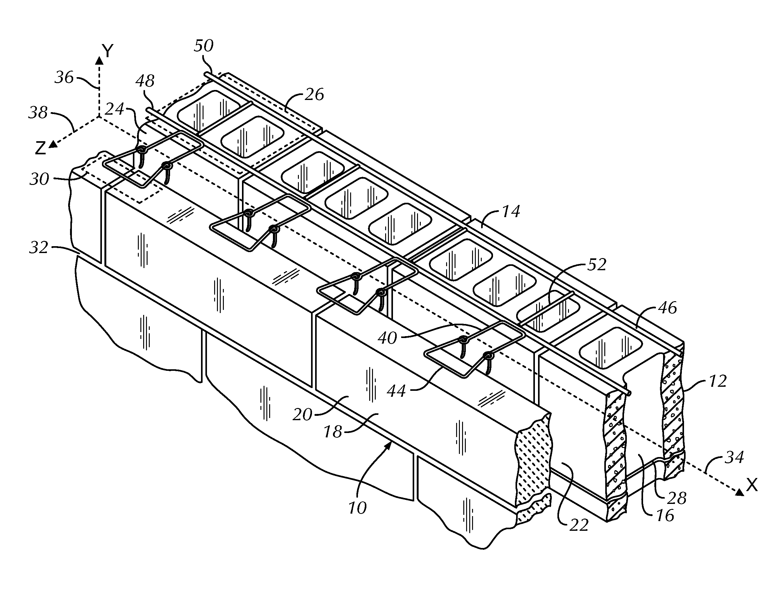
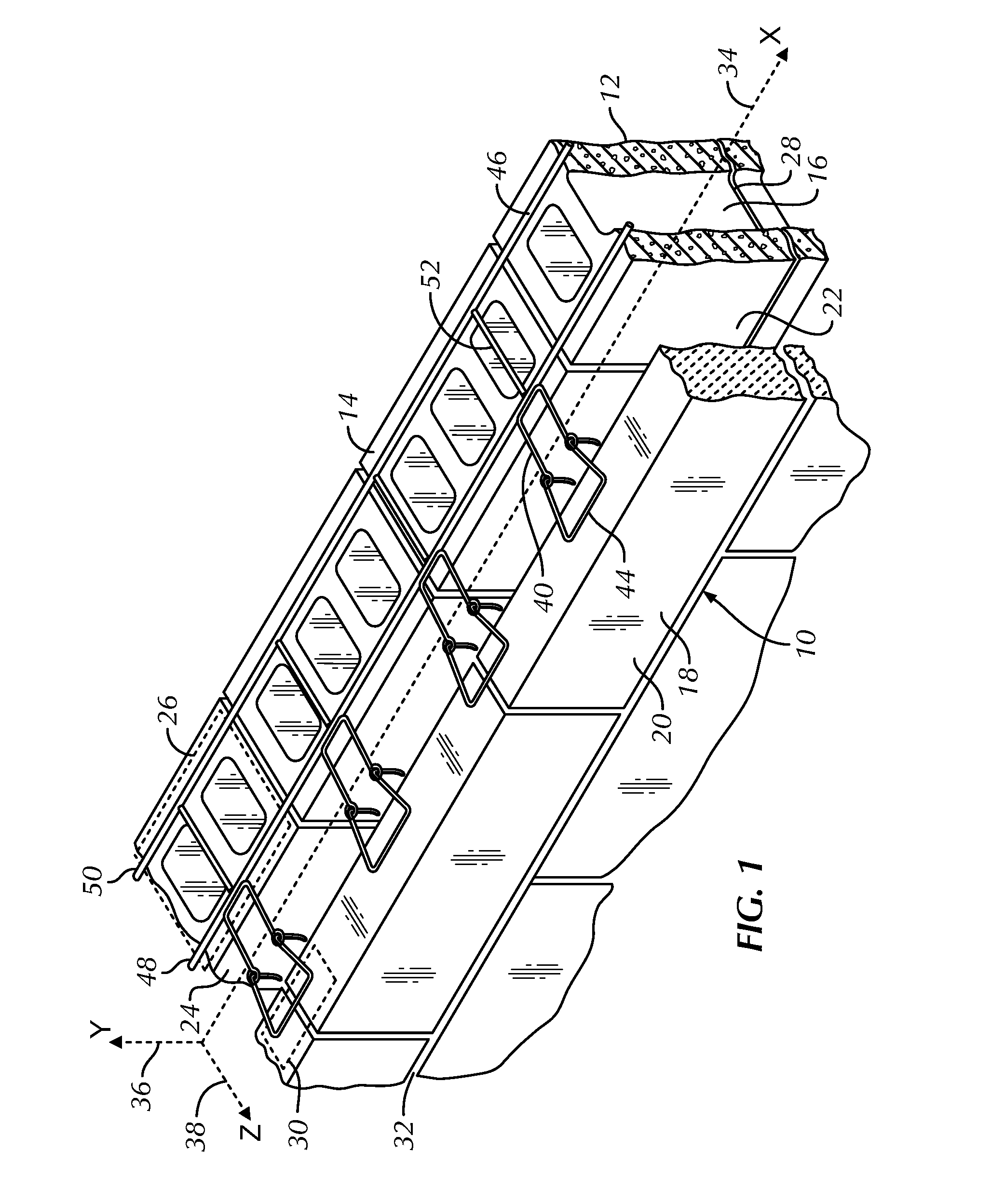
[0051]The description which follows is of three embodiments of anchoring systems utilizing the high-strength pintle veneer tie devices of this invention, which devices are suitable for nonseismic and seismic cavity wall applications. Two of the embodiments apply to cavity walls with masonry block inner wythes, and the remaining embodiment to a cavity wall with a dry wall (sheetrock) inner wythe. The wall anchor of the first embodiment is adapted from that shown in U.S. Pat. No. 6,789,365 of the inventors hereof.

[0052]Referring now to FIGS. 1 through 4 the first embodiment of the anchoring system hereof including a high-strength veneer tie of this invention is shown and is referred to generally by the number 10. In this embodiment, a wall structure 12 is shown having a backup wall or inner wythe 14 of masonry blocks 16 and a veneer facing or outer wythe 18 of facing brick or stone 20. Between the backup wall 14 and the facing wall 18, a cavity22 is formed, which cavity 22 extends out...

second embodiment

[0065]In the second embodiment in adapting the veneer tie 144 for high-strength applications, it is noted that the above-described arrangement of wire formatives is strengthened by the cold working thereof. In the past, while compressively altering wire formatives is taught by the patents of the inventors hereof, namely, U.S. Pat. Nos. 6,668,505 and 7,017,318, the teaching is to reduce the height of the wire formative inserted into the bed joint or between insulative panels. In this invention, in contrast to these past inventions, the compressive altering of wire formatives is found to enhance the strength of existing specified wire formatives to create anchoring systems with superior resistance to environmental forces, especially those exerted substantially normal to the exterior face of the outer wythe.

[0066]The ribbon pintles portions 162 and 164 of veneer tie 144 are considerably compressed and, while maintaining the same mass of material per linear unit as the adjacent wire for...

third embodiment

[0068]Referring now to FIGS. 6 to 8, the high-strength pintle anchoring system is shown and is referred to generally by the numeral 210. The system 210 employs a sheetmetal wall anchor 240, Catalog #HB-200 manufactured by Hohmann and Barnard, Inc., a MiTek-Berkshire Hathaway company, Hauppauge, N.Y. 11788. The dry wall structure 212 is shown having an interior wythe 214 with a wallboard 216 as the interior and exterior facings thereof. An exterior or outer wythe 218 of facing brick 220 is attached to dry wall structure 212 and a cavity 222 is formed therebetween. The dry wall structure 212 is constructed to include, besides the wallboard facings 216, vertical channels 224 with insulation layers 226 disposed between adjacent channel members 224. Selected bed joints 228 and 230 are constructed to be in cooperative functional relationship with the veneer tie described in more detail below.

[0069]For purposes of discussion, the exterior surface 232 of the interior wythe 214 contains a ho...


PUM


Abstract

A high-strength ribbon pintle and cavity wall anchoring system employing the same is disclosed. The ribbon pintle is a wire formative construct that is cold-worked with the resultant body having substantially semicircular edges and flat surfaces therebetween. The edges are aligned to receive compressive forces transmitted from the outer wythe. The ribbon pintles hereof, when part of the anchoring system, interengage with receptor portions of a wall anchor and are dimensioned to preclude significant movement lateral with or normal to the inner wythe.

Description

BACKGROUND OF THE INVENTION[0001]1. Field of the Invention[0002]This invention relates to an improved anchoring arrangement for use in conjunction with cavity walls having an inner wythe and an outer wythe. More particularly, the invention relates to construction accessory devices, namely, veneer ties with high-strength ribbon pintles. The veneer ties are for emplacement in the outer wythe and are further accommodated by receptors in the cavity, which receptors extend from the inner wythe to encapture the specially configured pintles hereof. The invention is applicable to structures having an outer wythe of brick or stone facing in combination with an inner wythe of either masonry block or dry wall construction.[0003]2. Description of the Prior Art[0004]In the past, investigations relating to the effects of various forces, particularly lateral forces, upon brick veneer masonry construction demonstrated the advantages of having high-strength wire anchoring components embedded in the ...

Claims


Application Information

Patent Timeline
Patent Type & Authority Applications(United States)
IPC IPC(8): E04C5/12E04C5/16
CPCE04B1/4185E04B1/4178
Inventor HOHMANN, JR., RONALD P.
Owner HOHMANN & BARNARD INC
Why Eureka
Try Eureka