Gun mount for semi-automatic firearm

a semi-automatic firearm and gun mount technology, applied in the field of firearm accessories and methods, can solve the problems of general difficulty for handicapped individuals to participate, firearms are difficult to hold and control, and traditional techniques for bump firing are somewhat unsafe and notoriously inaccurate. to achieve the effect of more conducive to us

Inactive Publication Date: 2013-03-28
SLIDE FIRE SOLUTIONS
View PDF0 Cites 22 Cited by
  • Summary
  • Abstract
  • Description
  • Claims
  • Application Information

AI Technical Summary

Benefits of technology

[0009]The present invention enables shooting enthusiasts to practice new and interesting ways to shoot firearms in a legal and safe manner, and is substantially more conducive to use by handicapped shooters.

Problems solved by technology

Although able to achieve a high rate of firing, traditional techniques for bump firing are somewhat unsafe and notoriously inaccurate.
Another issue with traditional bump firing techniques relates to the general difficulty for handicapped individual to participate.
Because of the unnatural and unbalanced firing grip, the firearm is very difficult to hold and control during the traditional bump firing methods.
As is too often the case, some have sustained disabling injuries.

Method used


Image

  • Gun mount for semi-automatic firearm
  • Gun mount for semi-automatic firearm
  • Gun mount for semi-automatic firearm

Examples


Embodiment Construction

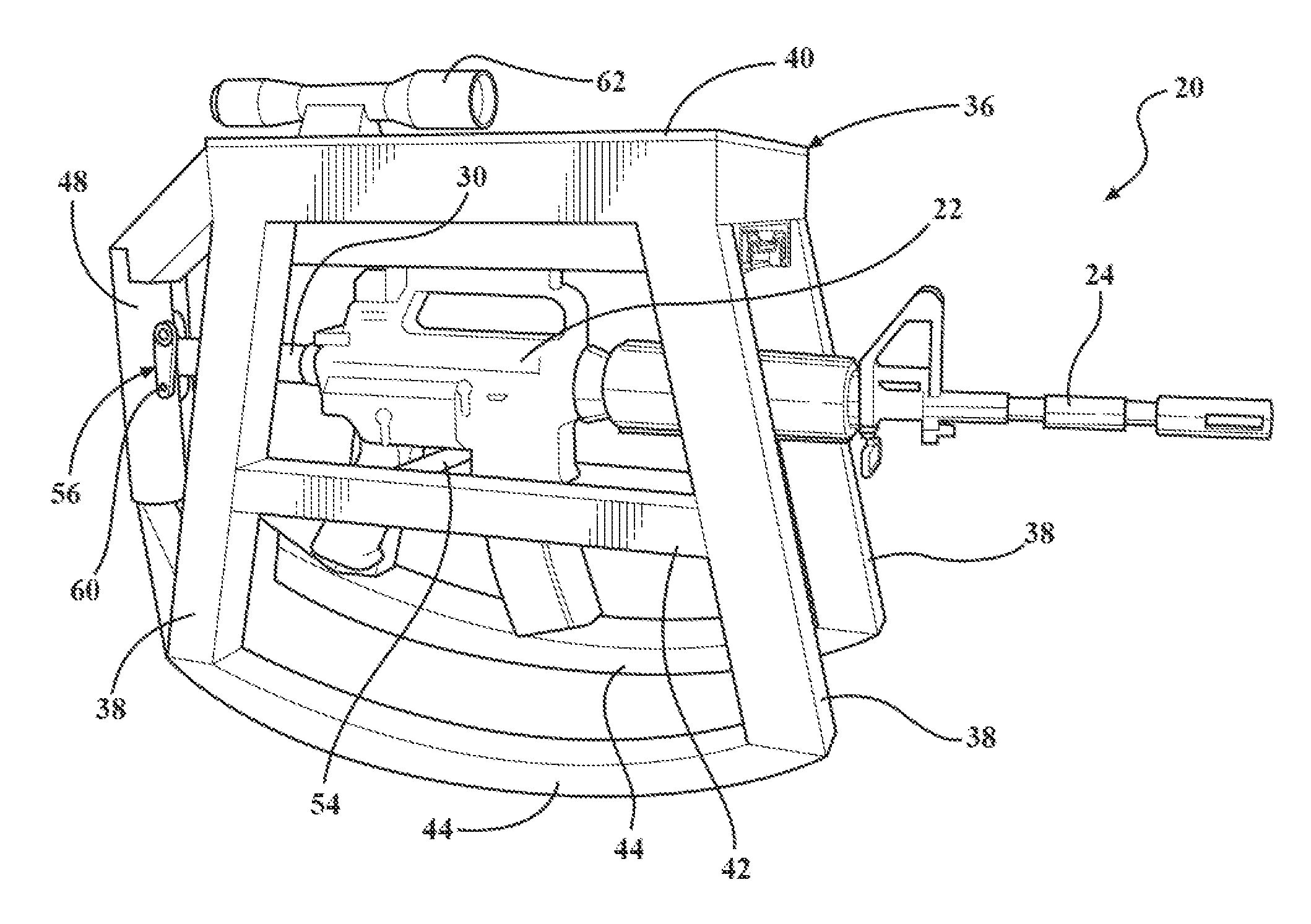
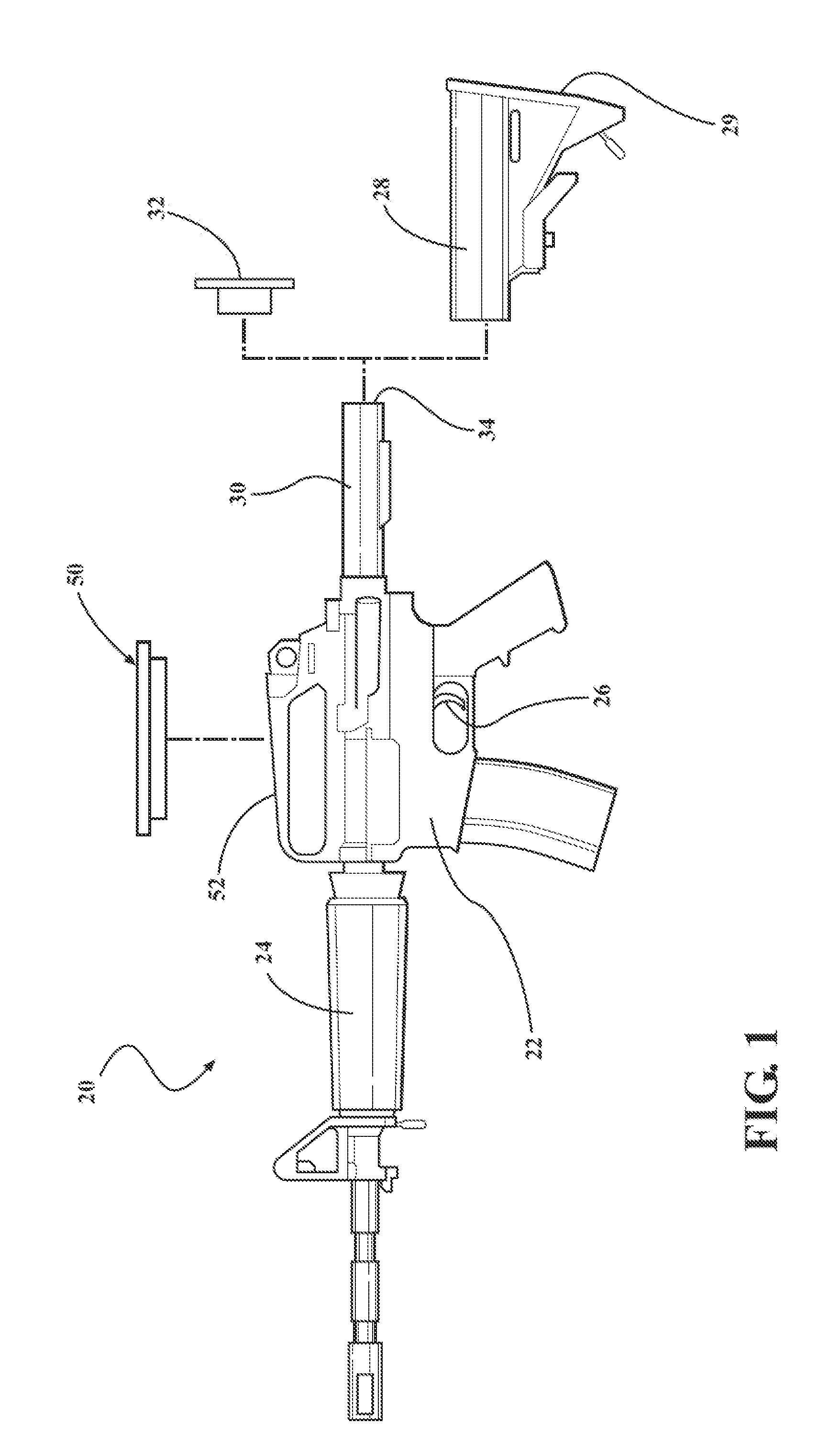
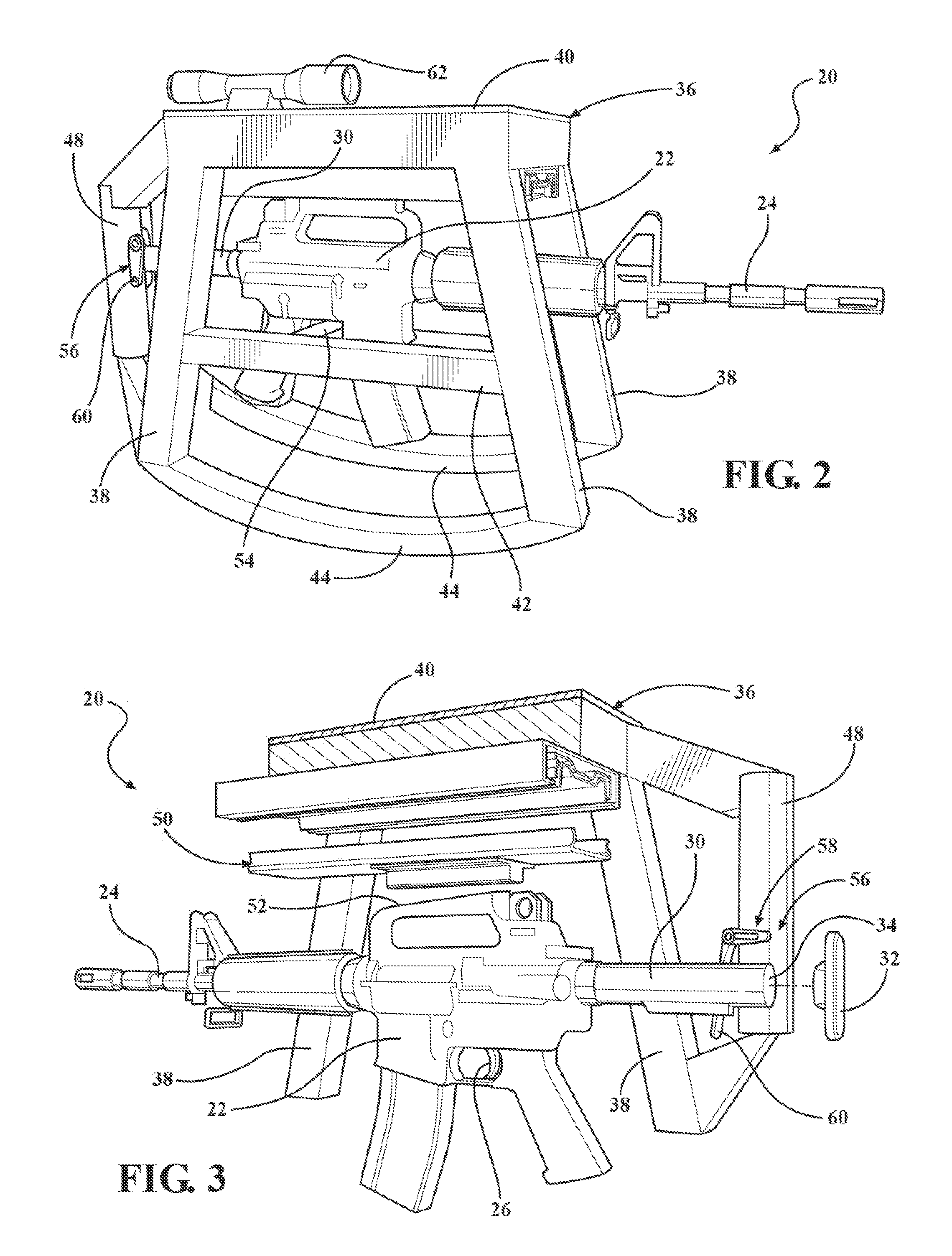
[0024]Referring to FIGS. 1-5, wherein like numerals indicate like or corresponding parts throughout the several views, a typical sporting-type semi-automatic firearm is shown at 20. The firearm 20 includes a receiver 22 for chambering a round of ammunition, a barrel 24 extending forwardly from the receiver 22, and a trigger group 26 supported in the receiver 22. The trigger group 26, or informally just “trigger”26, is configured so that when it is pulled rearwardly it activates a firing pin (not shown) that in turn strikes the primer of a chambered round of ammunition disposed in a breech portion of the receiver 22 and / or barrel 24, thus discharging the projectile portion (i.e., bullet) through the barrel 24 and downrange toward an intended target. The firearm 20 may also include additional features like sighting devices, guards, straps, and the like as will be readily understood by those of skill in the art, some of which are described in greater detail below. The receiver 22 and b...


PUM


Abstract

A mount assembly for a semi-automatic firearm supports the weight of a firing unit (receiver, barrel and trigger) in a slide stand on or from a support structure so that a user does not have to bear any or at least a significant portion of the firearm's weight. Through a sliding interface, the firing unit is manually pushed by a user's thumb(s) to slide forward in the slide stand until a trigger actuator depresses the trigger. The trigger actuator may include a rod or a rest for a user's finger. Recoil energy from a discharged bullet pushes the firing unit rearwardly back to the starting position. The slide stand can include a convex or articulating base for variable aiming, or a fixed base for sharp-shooting.

Description

CROSS REFERENCE TO RELATED APPLICATIONS[0001]This application claims priority to Provisional Patent Application No. 611560379 filed Nov. 16, 2011, and this application is a Continuation-In-Part of U.S. Ser. No. 13 / 464,669, filed May 4, 2012, which is a Continuation of U.S. Ser. No. 13 / 335,731, filed Dec. 22, 2011, now U.S. Pat. No. 8,176,835, which is a Continuation-In-Part of U.S. Ser. No. 13 / 281,808, filed Oct. 26, 2011, now U.S. Pat. No. 8,127,658, which is a continuation-In-Part of U.S. Ser. No. 12 / 949,002, filed Nov. 18, 2010, now U.S. 2011 / 0113665, which claims the benefit. of U.S. Provisional Application Ser. No. 61 / 262,315 filed Nov. 18, 2009, the entire collective disclosures of which are hereby incorporated by reference and relied upon.BACKGROUND OF THE INVENTION[0002]1. Field of the Invention[0003]The present invention relates generally to an apparatus and method for shooting firearms, and more particularly toward an improved gun mount in which the weight of a semi-automa...

Claims


Application Information

Patent Timeline
Patent Type & Authority Applications(United States)
IPC IPC(8): F41A19/06F41A17/00F41A23/02
CPCF41A19/06F41A23/02F41A17/00F41A19/11F41A23/10F41C23/14F41C23/16F41C23/20F41A19/10F41C23/04
Inventor COTTLE, JEREMIAH
Owner SLIDE FIRE SOLUTIONS
Why Eureka
Try Eureka