Milking robot, and a milking arrangement

a technology of milking robots and milking trays, which is applied in the field of milking robots, can solve the problems of industrial robots that can run out of control, unsafe, and singularities, and achieve the effects of simple, inexpensive and light design, and proper accuracy

Active Publication Date: 2013-03-28
DELAVAL HLDG AB
View PDF4 Cites 10 Cited by
  • Summary
  • Abstract
  • Description
  • Claims
  • Application Information

AI Technical Summary

Benefits of technology

[0007]The object of the invention is to provide a milking robot with a simple, inexpensive and light design. Furthermore, the object of the invention is to provide such a milking robot which is safe, and which can be used among animals and people without exposing them to any danger. In addition, it is aimed at a milking robot that is compliant with regard to forces exerted by the animal and rigid so that a proper accuracy can be achieved.
[0009]By such a restriction to the movements of the first, second and third link it can be ensured that no singularity can occur. The milking robot according to the invention is thus safe in the sense that the movement of the links to any arbitrary position within the workspace can be predicted. The restriction of the movements are achieved by limiting the number of axes (degrees of freedom) and / or by limiting the angle ranges.
[0010]Thanks to the limited number of links, the manufacturing costs of the milking robot can be relatively low, and the design can be relatively light and simple.
[0019]According to a further embodiment of the invention, the first link has a first active length, the second link a second active length and the third link a third active length, wherein the second and third active lengths are at least twice the first active length or wherein the first and second active lengths are at least twice the third active length. By providing two of the links with a relatively long length, the variation of the angle of the gripper can be reduced or minimized, which improves the possibility of the sensor to sense the teats of the animal.
[0020]According to a further embodiment of the invention, the first joint actuator, the second joint actuator and the third joint actuator comprise a first, second and a third, respectively, compliance means configured to permit movement of the respective link in response to an externally exerted force when the external force exceed a predetermined value. Consequently, the milking robot will be compliant with regard to large forces exerted by the animal so that the risk of damaging the milking robot is reduced. Advantageously, the first joint actuator, the second joint actuator and the third joint actuator comprise a respective hydraulic actuator operated by means of a hydraulic medium, wherein the compliance means comprise at least one overflow valve configured to open for the hydraulic medium when the external force exceeds the predetermined value.

Problems solved by technology

One known problem of industrial robots is the phenomenon of singularities.
If a singularity occurs, the industrial robot can run out of control, and is thus not safe.
However, due to the gripper being rotatable around the second turning axis a singularity does occur.
Consequently, the design shown in EP-A-900 522 can not be regarded as sufficiently safe in all possible situations that can occur in a milking stall and during a milking operation.

Method used


Image

  • Milking robot, and a milking arrangement
  • Milking robot, and a milking arrangement
  • Milking robot, and a milking arrangement

Examples


first embodiment

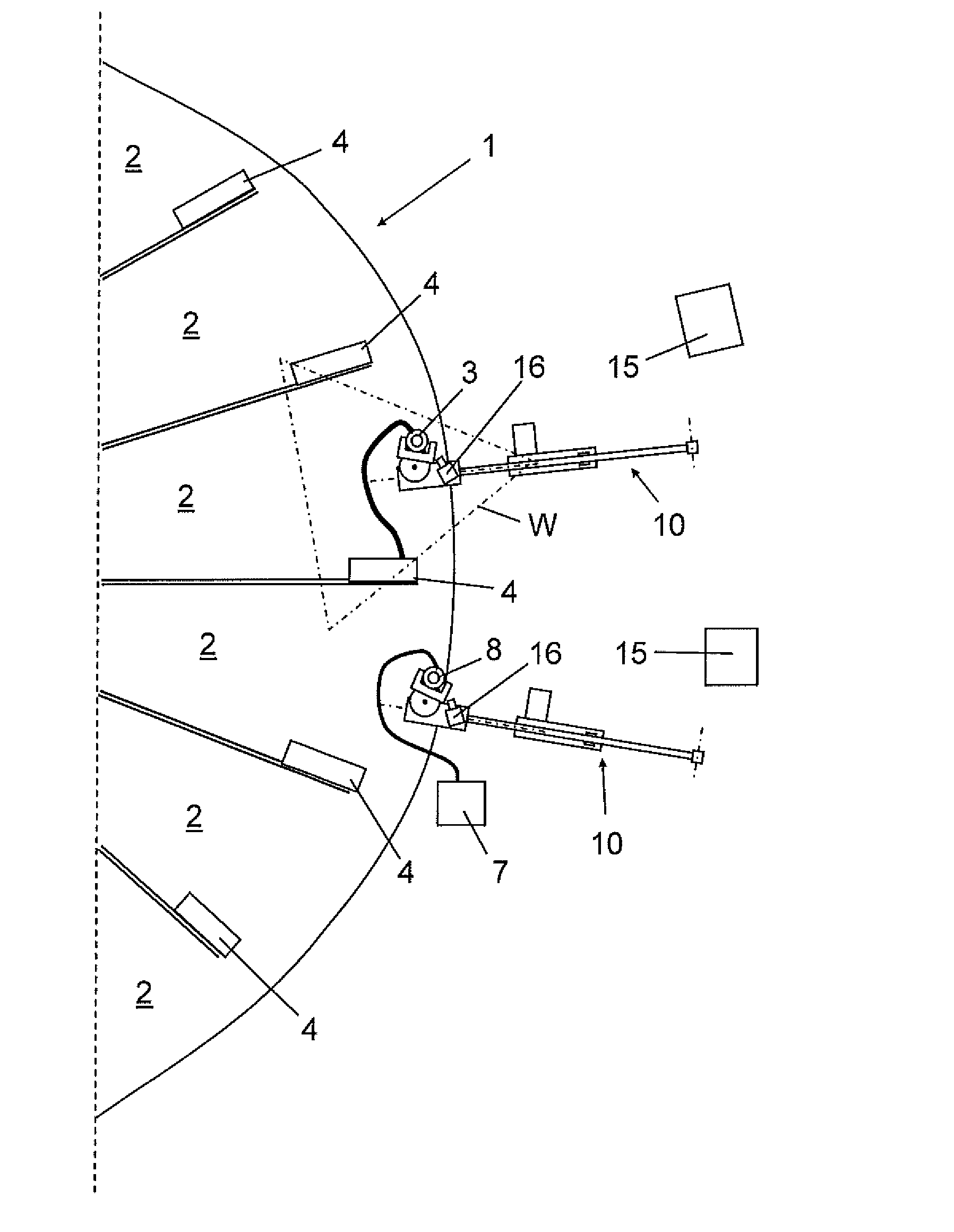
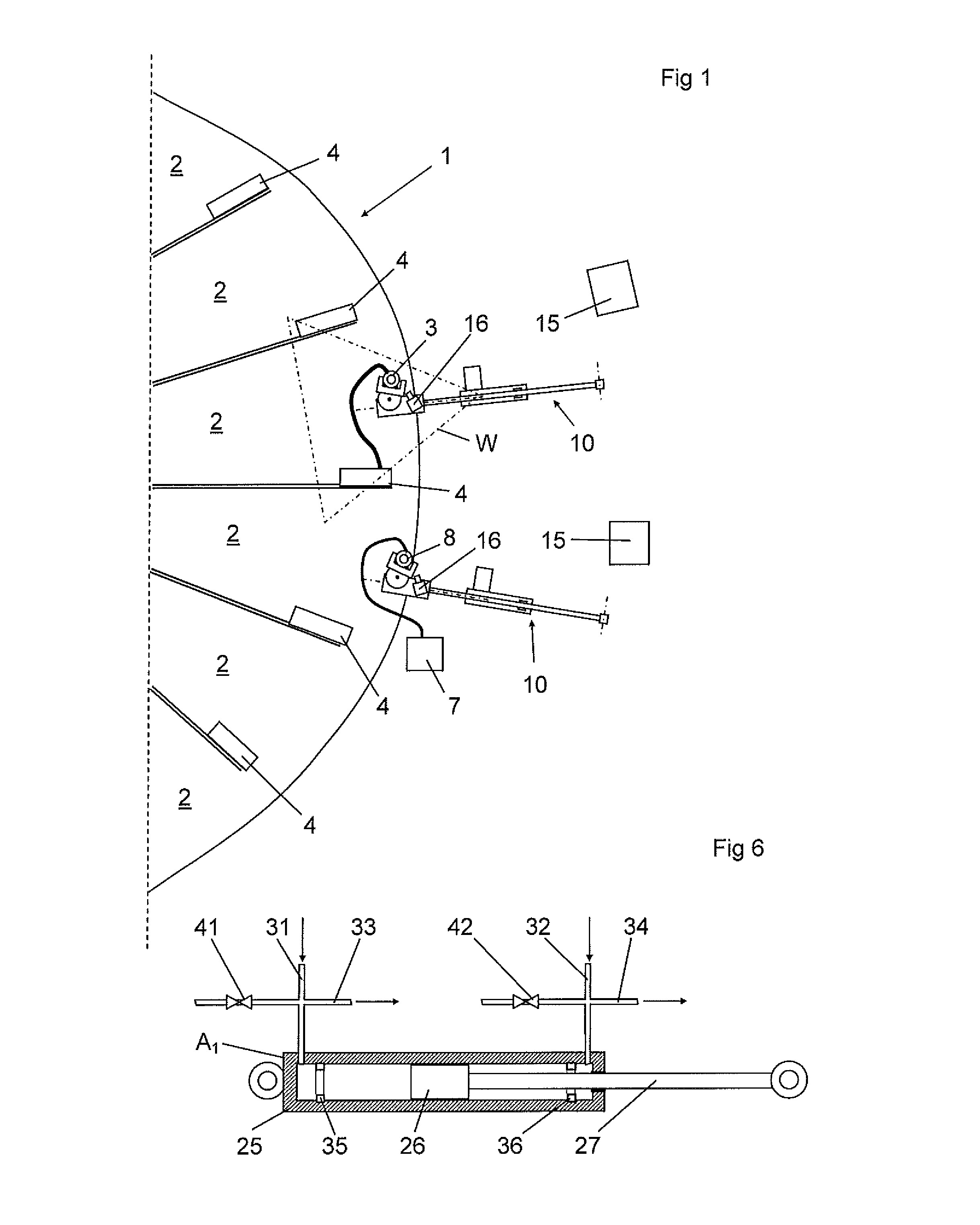
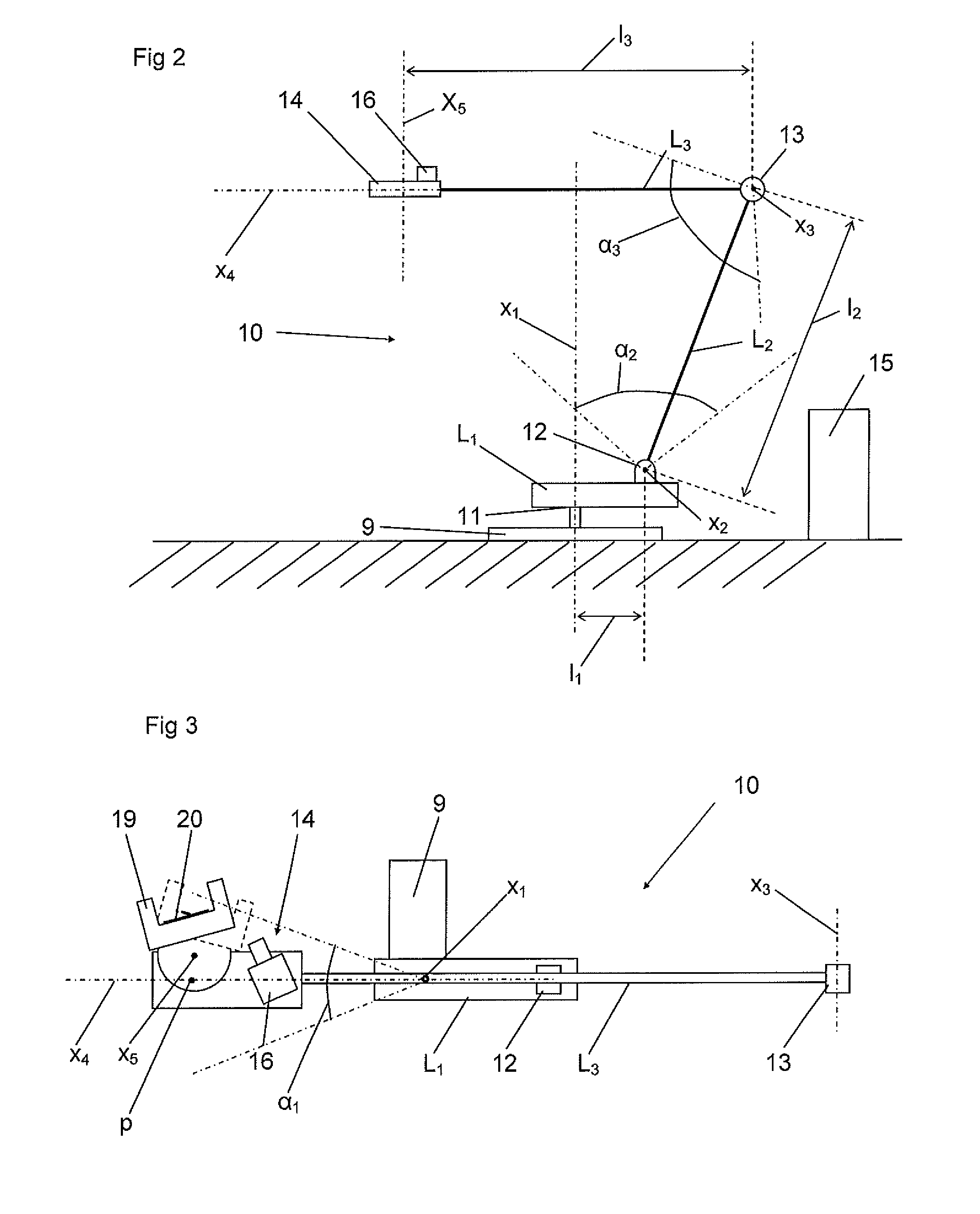
[0037]The configuration of the milking robot 10 is now to be explained more closely with reference to FIGS. 2-6. As can be seen the milking robot 10 is a three link robot with three axes, and comprises a first link L1, a second link L2 and a third link L3. The first link L1 is attached to a base member 9 and rotatable around a first axis x1 to a first angle within a first angle range α1 via a first joint 11 by means of a first joint actuator A1. The second link L2 is attached to the first link L1 and rotatable around a second axis x2 to a second angle within a second angle range α2 via a second joint 12 by means of a second joint actuator A2. The third link L3 is attached to the second link L2 and rotatable around the third axis x3 to a third angle within a third angle range α3 via a third joint 13 by means of a third joint actuator A3. The base member 9 may be mounted on the ground.

[0038]The first link L1 is rotatable around the first axis x1 within the first angle range α1 with re...

second embodiment

[0056]As can be seen in FIGS. 7 and 8, the first link L1 is thus attached to a base member 9 and rotatable around a first axis x1 to a first angle within a first angle range α1 via a first joint 11 by means of a first joint actuator A1, disclosed in FIGS. 9 and 10. In the second embodiment, the first axis x1 extends horizontally or substantially horizontally.

[0057]The second link L2 is attached to the first link L1 and rotatable around a second axis x2 to a second angle within a second angle range α2 via a second joint 12 by means of a second joint actuator A2, disclosed in FIGS. 9 and 10. In the second embodiment, the second axis x2 extends horizontally or substantially horizontally.

[0058]The third link L3 is attached to the second link L2 and rotatable around the third axis x3 to a third angle within a third angle range α3 via a third joint 13 by means of a third joint actuator A3, disclosed in FIGS. 9 and 10 In the second embodiment, the third axis x3 extends vertically or substa...


PUM


Abstract

A milking arrangement includes a milking robot (10) having a first link (L1), a second link (L2), a third link (L3), an end effector (E), sensor (16) and a control unit (15). The first link is rotatable to a first angle within a first angle range (α1) via a first joint (11). The second link is rotatable to a second angle within a second angle range (α2) via a second joint (12). The third link (L3) is rotatable to a third angle within a third angle range (α3) via third joint (13). The links (L1, L2, L3) are rotatable so that the end effector is movable within a three-dimensional workspace (W). Each position of the end effector within the workspace corresponds to a single combination of the first, second and third angles.

Description

BACKGROUND OF THE INVENTION AND PRIOR ART[0001]The present invention refers to a milking robot for handling teatcups of a milking machine and cleaning cups for cleaning the teats of an animal prior to milking. The milking robot is especially configured for attaching the cleaning cup and / or the teatcups to the teats of the animal. More precisely, the invention refers to a milking robot according to the pre-characterizing part of claim 1. The invention also refers to a milking arrangement.[0002]It is known to use industrial robots within the manufacturing industry. It is also known to use an industrial robot as a so called milking robot in connection with milking of animals, see for instance EP-A-900 522.[0003]An industrial robot is, according to the European Standard EN ISO 10218-1:2008, an automatically controlled, reprogrammable multipurpose manipulator, programmable in three or more axes, which may be either fixed in place or mobile for use in industrial automation applications.[0...

Claims


Application Information

Patent Timeline
Patent Type & Authority Applications(United States)
IPC IPC(8): A01J5/00
CPCA01J5/0175B25J9/101A01J5/007A01J5/003A01J5/00
Inventor ANDERSSON, JAN-ERIKAXELSSON, THOMAS
Owner DELAVAL HLDG AB
Why Eureka
Try Eureka