Patient interface and headgear

a patient interface and headgear technology, applied in the field of patient interface and headgear, can solve the problems of patient not willingly to tolerate the mask for the desired long duration, patient is often required to wear the interface continuously for hours or perhaps even days, and the patient cannot achieve good seals

Active Publication Date: 2013-03-28
FISHER & PAYKEL HEALTHCARE LTD
View PDF9 Cites 98 Cited by
  • Summary
  • Abstract
  • Description
  • Claims
  • Application Information

AI Technical Summary

Benefits of technology

[0011]Because the interface may be worn for prolonged periods in a hospital for example or when sleeping, comfort preferably should be maximized while also maintaining sufficient pressure on the interface to provide proper location and an adequate seal against the face, thereby reducing the likelihood of significant leaks. For example, any leakage preferably is less than about 15 L / min. In a hospital setting, it is also possible that a patient will not be conscious while wearing the interface. Added comfort can also increase the patient's compliance with treatment and results in better outcomes generally.
[0197]According to a further aspect, the headgear assembly including a first lower connecting strap and a second lower connecting strap extending away from the first strap portion, at least a portion of the first and second lower connecting straps being semi-rigid whereby the first and second lower connecting straps are adapted to present laterally outward or forward when the lower rear region is positioned on the head such that the first lower connection strap and the second lower connecting strap are less likely to tangled behind the head when the headgear assembly is positioned on the head.

Problems solved by technology

In many interfaces, a good seal often is attained only with considerable discomfort for the patient, with temporary success and / or with significant time spent fitting the interface to the patient.
In such environments, the patient will be required to wear the interface continuously for hours or perhaps even days.
If significant discomfort is experienced, the patient will not willingly tolerate the mask for the desired long durations.
In many constructions, even a good seal can be temporary due to an inability to seal effectively when the face of the patient becomes distorted.
The twisting of the axis can result in leakage on one side of the interface.
In addition, a side-sleeping patient may also distort the facial contours (e.g., in the nasal area) around the seal, which may lead to further leakage.

Method used


Image

  • Patient interface and headgear
  • Patient interface and headgear
  • Patient interface and headgear

Examples


Embodiment Construction

Overall System

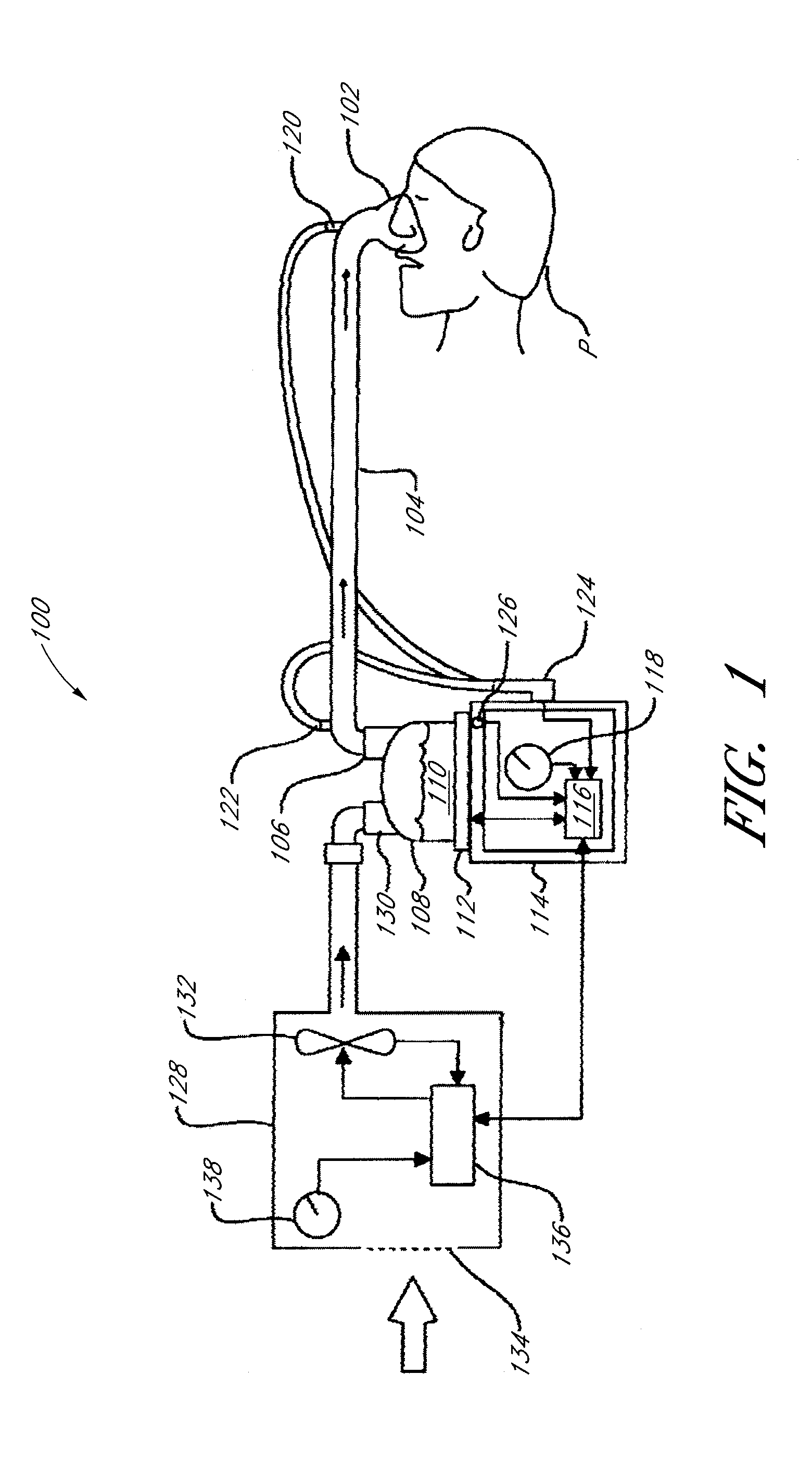
[0250]With reference to FIG. 1, a humidified positive airway pressure (PAP) system 100 is shown in which a patient P, or other user, is receiving humidified and pressurized gases through a patient interface 102. The PAP system 100 can be continuous, variable or bi-level positive airway pressure or any other suitable form of respiratory therapy. In some configurations, the PAP system 100 could be or include a hospital ventilator or any other suitable form of respiratory therapy. In some applications, the interface 102 can be used with non-humidified PAP systems.

[0251]The interface 102 connects to a conduit that defines a humidified gases transportation pathway or inspiratory breathing tube 104, for example. The conduit 104 may contain heating means or a heater wire (not shown) that heats the gases or the walls of the conduit to reduce condensation of humidified gases within the conduit.

[0252]The conduit 104 connects to an outlet 106 of a humidification chamber 108. The ...


PUM


Abstract

Patient interface components and / or associated head gear and adjustment systems improve sealing and / or patient comfort and / or ease of use. The interface comprising an inflating or ballooning seal. The headgear assembly can be connected to the interface with an elastic component and an inelastic component. The elastic component enabling a course fitting of the interface to the patient and the inelastic component enabling a final fitting of the interface to the patient.

Description

CROSS-REFERENCE TO RELATED APPLICATIONS[0001]This application claims the priority benefit under 35 U.S.C. §119(d) of U.S. Provisional Application No. 61 / 289,641, filed on Dec. 23, 2009, and of U.S. Provisional Application No. 61 / 391,514, filed on Oct. 8, 2010, each of which is hereby incorporated by reference in its entirety.BACKGROUND OF THE INVENTION[0002]1. Field of the Invention[0003]The present invention relates to improved patient interface components, particularly but not solely, for use in delivering artificial respiration therapy to patients. In particular, the invention relates to interfaces and to headgear that is used to secure interfaces to a patient[0004]2. Description of the Related Art[0005]In the art of respiration devices, there are a variety of respiratory interfaces that cover the nose and / or mouth of a patient in order to provide a seal around the nasal and / or oral areas of the face such that gas may be provided at positive pressure within the interface for cons...

Claims


Application Information

Patent Timeline
Patent Type & Authority Applications(United States)
IPC IPC(8): A61M16/06A61M16/00
CPCA61M16/06A61M16/0616A61M16/0057A61M16/0683A61M16/0003A61M16/0816A61M16/0825A61M16/0858A61M16/00A62B9/00A62B18/00A61M16/0605A61M16/0627A61M2016/0661
Inventor SMITH, DANIEL JOHNHUDDART, BRETT JOHNADAMS, MATTHEW JAMESHOBSON, NICHOLAS ALEXANDERSHARP, TIMOTHY JAMES BERESFORDPATEL, ROHEETOLSEN, GREGORY JAMESSTEPHENSON, MATTHEW ROGERBARSTEN, TROY
Owner FISHER & PAYKEL HEALTHCARE LTD
Why Eureka
Try Eureka