Toolrest mechanism for wood turning lathe

a toolrest and lathe technology, applied in the field of wood turning lathes, can solve the problems of unstable engagement of the carriage to the toolrest b>9/b>, and risk the worker's hand cutting with the tool, so as to achieve the effect of avoiding or at least improving the instability of the engagemen

Inactive Publication Date: 2013-03-28
CHOU CALVIN
View PDF6 Cites 24 Cited by
  • Summary
  • Abstract
  • Description
  • Claims
  • Application Information

AI Technical Summary

Benefits of technology

[0008]Thus the primary objective of the present invention is achieved by the retaining force applied to the shaft of the toolrest circumferentially via a periphery of the retaining socket from the clamping elements. When tightly sandwiched between the clamping elements, the shaf

Problems solved by technology

However, since the force such applied acts unilaterally on the shaft 11 when the bolt 10 is fully screwed toward the shaft 11, the engagement of the carriage 8 to the toolrest 9 is not stable and tends to fail when the toolrest mechanism 6 receives a cou

Method used


Image

  • Toolrest mechanism for wood turning lathe
  • Toolrest mechanism for wood turning lathe
  • Toolrest mechanism for wood turning lathe

Examples


Embodiment Construction

[0017]While a preferred embodiment is provided herein for illustrating the concept of the present invention as described above, it is to be understood that the components in these drawings are made for better explanation and need not to be made in scale. Moreover, in the following description, resemble components are indicated by the same numerals.

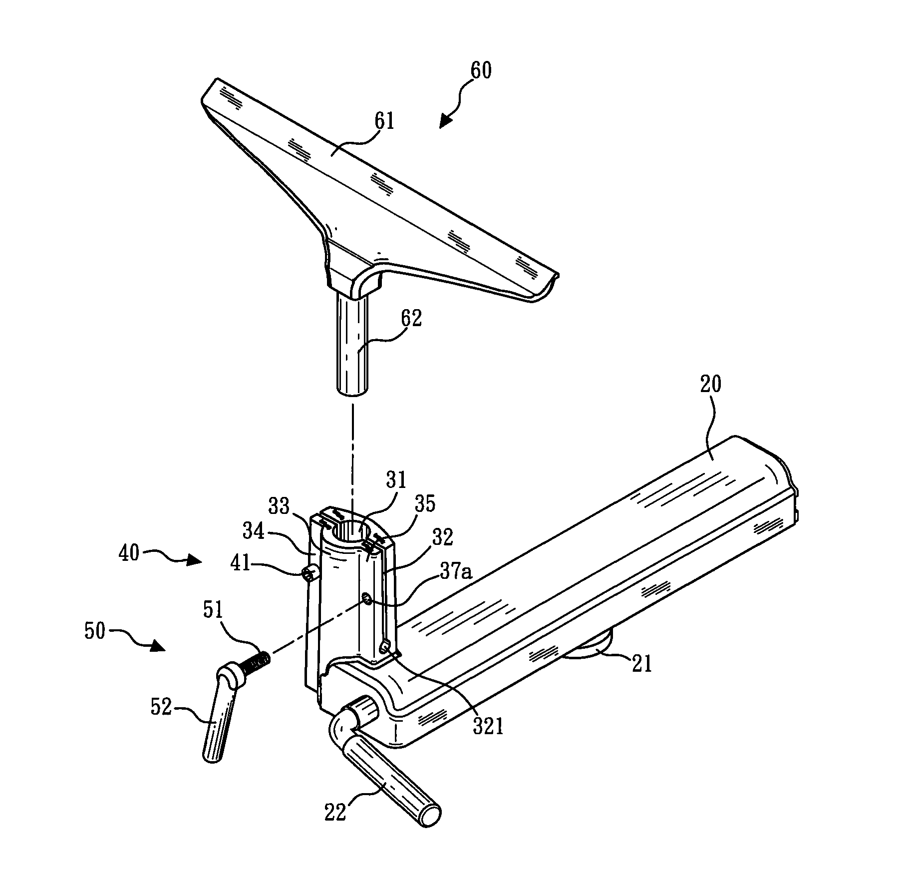
[0018]Please refer to FIGS. 4-7. According to one preferred embodiment of the present invention, a toolrest mechanism for a wood turning lathe includes a banjo 20, a carriage 30, a first threaded element 40, a second threaded element 50 and a toolrest 60.

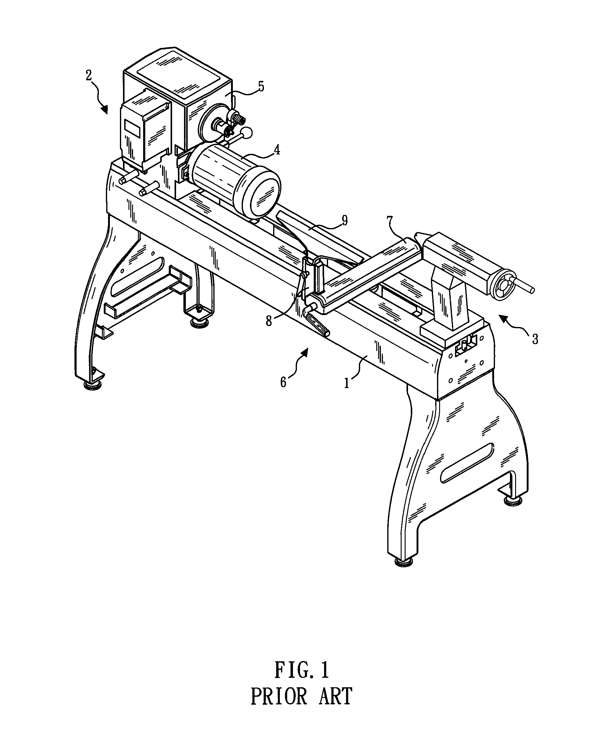
[0019]The banjo 20 is adapted to sit across a lathe bed 1 of the wood turning lathe, as that shown in FIG. 1. Preferably, the banjo 20 is slidable along the length direction of the lathe bed 1, and a sliding cam 21 can be further provided beneath the banjo 20. The sliding cam 21 can be actuated by a lever 22 so as to selectively affix the banjo 20 on the lathe bed 1.

[0020]The carriage 30 i...


PUM


Abstract

A toolrest mechanism for a wood turning lathe includes a banjo, a carriage, a first threaded element, a second threaded element and a toolrest. The carriage is divided into two clamping elements facing each other by a slot formed therebetween, and the clamping elements can be drawn together by operating the threaded elements, so as to adjust the carriage from an initial, release position toward a clamping position. The toolrest has a toolrest portion and a shaft. The shaft is allowed to move axially within the slot while the carriage is at the release position, and the shaft is disallowed to move axially within the slot while the carriage is at the clamping position.

Description

BACKGROUND OF THE INVENTION[0001]1. Technical Field[0002]The present invention relates to wood turning lathes, and more particularly to a toolrest mechanism provided to a wood turning lathe for supporting a manual tool to tool a workpiece turning on the lathe.[0003]2. Description of Related Art[0004]A wood turning lathe is a machine rotating a wood workpiece with its spindle. As shown in FIG. 1, the lathe substantially has a lathe bed 1, a headstock 2, a tailstock 3, a power source 4, a speed-changing mechanism 5 coupled to the spindle for turning the workpiece, and a toolrest mechanism 6. The headstock 2 and the tailstock 3 are disposed on both sides of the lathe bed 1 respectively and can support a wood workpiece affixed therebetween. The spindle of the headstock 2 is powered by the power source 4 via the speed-changing mechanism 5 to rotate the workpiece. At this time, a worker can manually hold a cutting tool and rest the tool against the toolrest mechanism 6 in order to stably ...

Claims


Application Information

Patent Timeline
IPC IPC(8): B27C7/06
CPCB27C7/06
Inventor CHOU, CALVIN
Owner CHOU CALVIN
Why Eureka
Try Eureka