Induced-Gas Flotation Cell with Horizontal Flow

a flotation cell and gas technology, applied in the direction of filtration separation, sedimentation settling tanks, separation processes, etc., can solve the problems of not being able to achieve a high volumetric use, not the most efficient separation method, and the inability to optimize the baffle to prevent water channeling

Inactive Publication Date: 2013-03-28
CAMERSON INT CORP
View PDF12 Cites 14 Cited by
  • Summary
  • Abstract
  • Description
  • Claims
  • Application Information

AI Technical Summary

Problems solved by technology

However, several problems exist: (1) the movement of water over and under the baffles can create turbulence which disperses the oil into small droplets that cannot be removed; (2) counter-current flow of water and gas is not the most efficient separation method for the smallest oil droplets; and (3) the baffles cannot be optimized to prevent water channeling and achieve a high volumetric use, with volumetric use often being less than 50%.

Method used


Image

  • Induced-Gas Flotation Cell with Horizontal Flow
  • Induced-Gas Flotation Cell with Horizontal Flow
  • Induced-Gas Flotation Cell with Horizontal Flow

Examples


Embodiment Construction

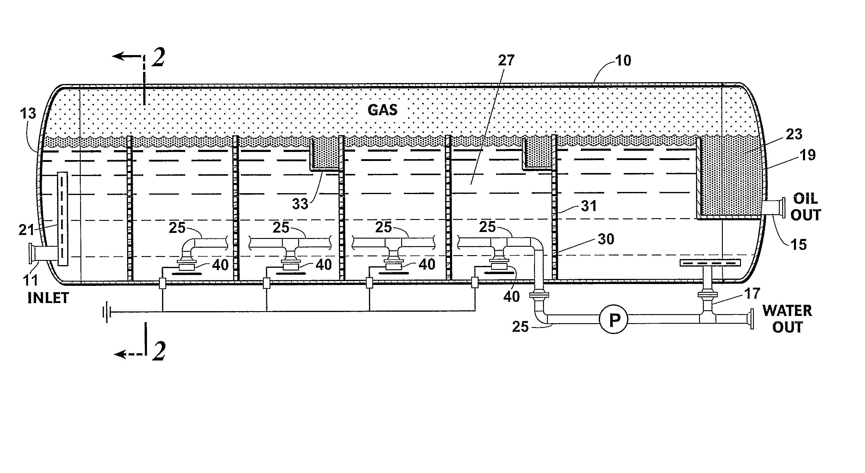
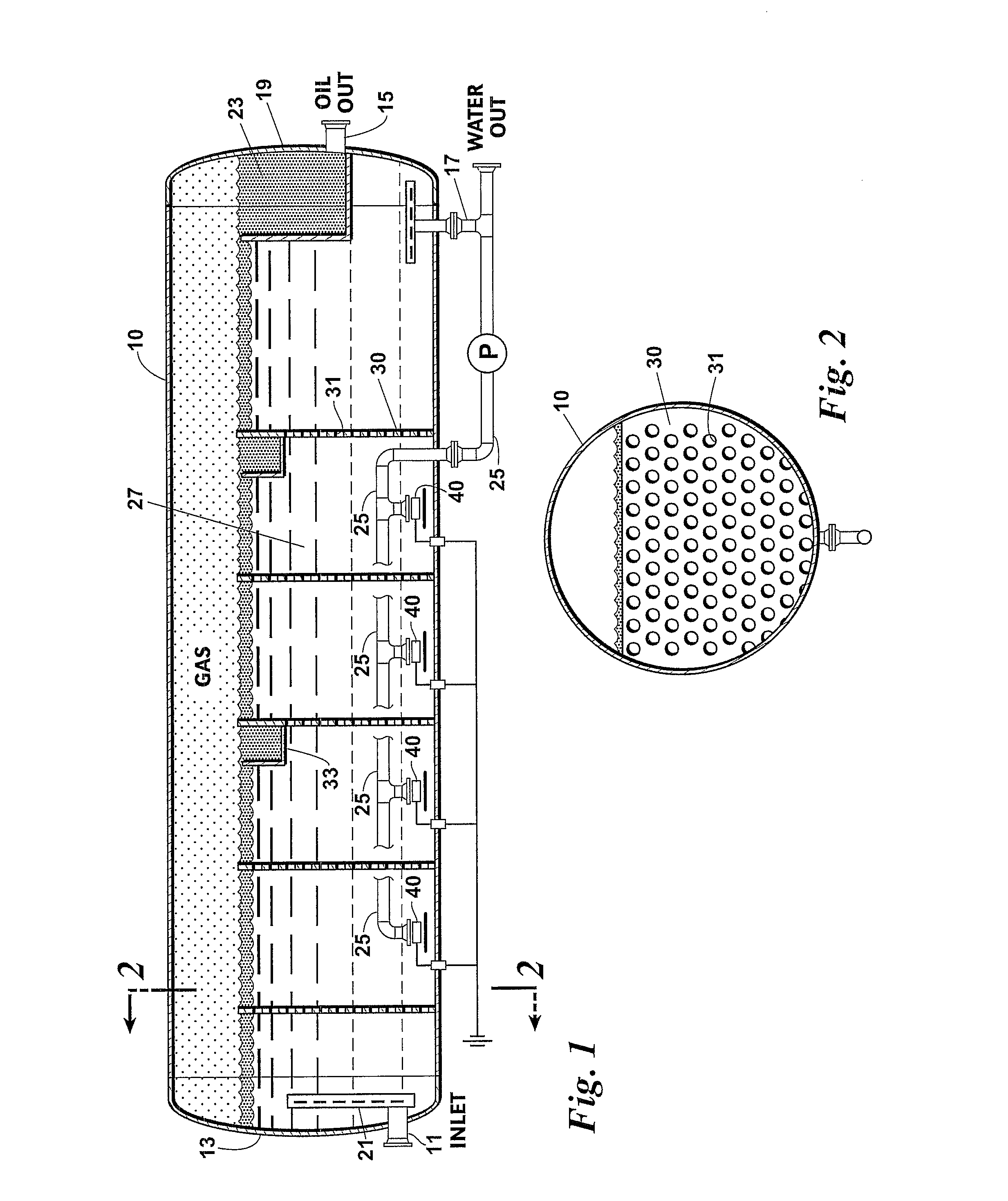
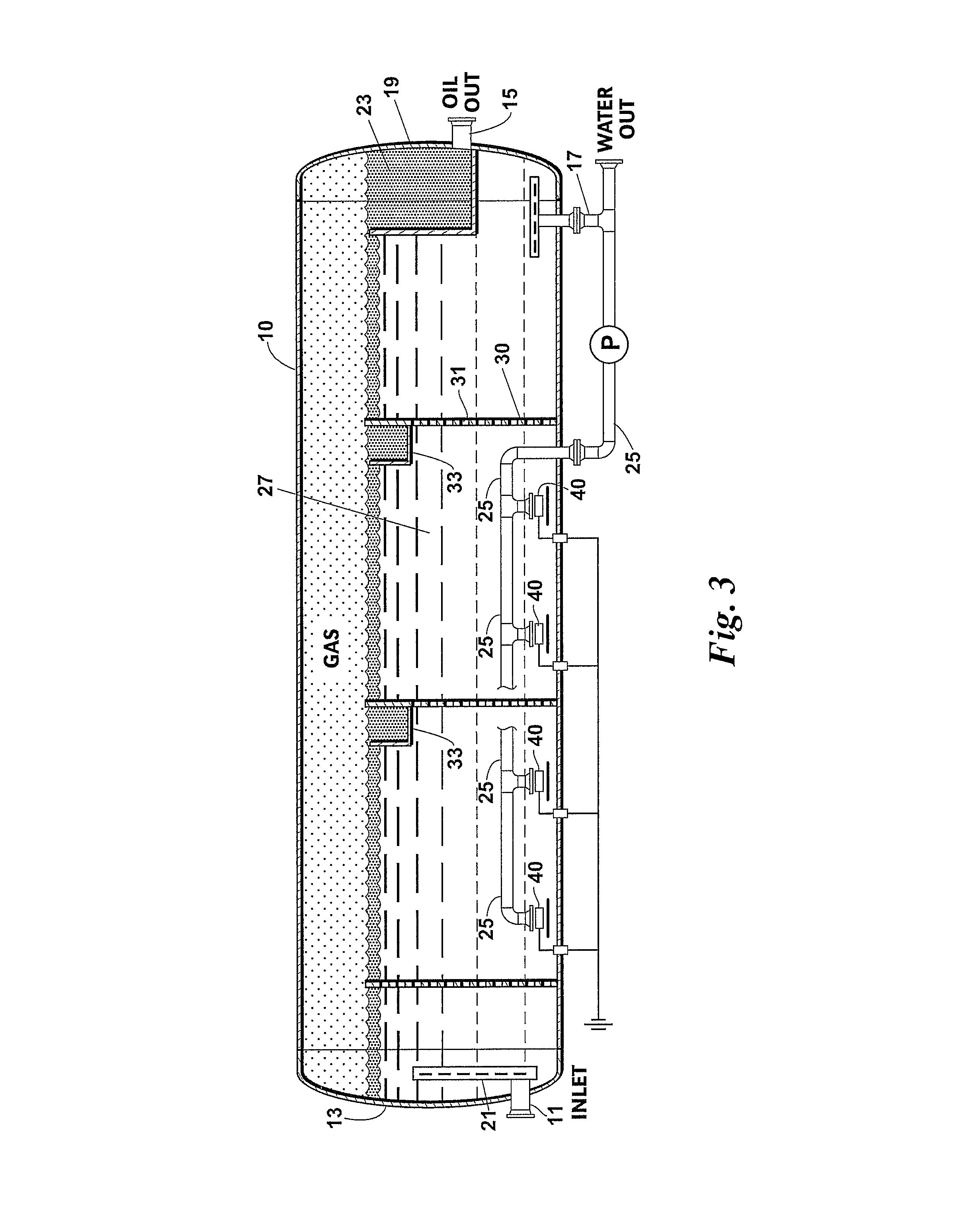
[0030]An induced-gas flotation cell made according to this invention includes an elongated, horizontally oriented separator vessel 10 of a kind used in the art and having a produced water inlet 11 at its first end 13 and an oil outlet 15 and a water outlet 17 located at its second end 19. Produced water inlet 11 is in communication with an inlet device 21 which functions to control the incoming momentum or velocity of the produced water stream entering the vessel 10 and create an initial, substantially horizontal flow of the incoming produced water stream. The produced water continues to flow from the first end 13 to the second end 19 in this same horizontal direction through a series of perforated baffles or plates 30. By controlling the momentum of the incoming produced water stream and converting it as rapidly as possible into smooth, horizontal flow, the damage done by the incoming stream to water droplets can be minimized and the volumetric utilization of vessel 10 can be maxim...


PUM

PropertyMeasurementUnit
diameteraaaaaaaaaa
velocityaaaaaaaaaa
widthaaaaaaaaaa

Abstract

An improved induced-gas separation vessel made according to this invention and method for its use includes an elongated, horizontally oriented vessel having compartments defined by adjacent pairs of perforated baffles which span the width but not the height of the vessel. One or more gas eductors are located within each compartment. An inlet device controls the momentum or velocity of the incoming water stream and rapidly converts it to horizontal flow prior to it encountering the first perforated baffle. The design of each baffle is such that the flow of water through each perforated baffle is a laminar or smooth flow without any change in direction. By controlling incoming velocity and providing perforated baffles, water distribution within the vessel is increased as is volumetric utilization. The total volumetric use of the vessel is at least 50% and can be as great as 80%.

Description

BACKGROUND OF THE INVENTION[0001]This invention generally relates to apparatuses and methods for separating oil from a produced water stream. More specifically, this invention relates to apparatuses and methods which make use of induced-gas flotation cells for separating oil from a produced water stream.[0002]Water produced in association with crude oil includes entrained contaminants such as residual oil and solids. Therefore, the water must be cleaned sufficiently of those contaminants prior to its disposal or injection. One of the more common cleaning methods involves introducing a natural gas flow through an eductor and into the produced water. The gas bubbles or droplets attach themselves to the oil, causing the oil to float to the surface of the water along with the gas. Controlling the gas droplet size and population can optimize oil removal efficiency. A detailed description of this method can be found in U.S. Pat. No. 7,157,007, titled “Vertical Gas Induced Flotation Cell” ...

Claims


Application Information

Patent Timeline
Patent Type & Authority Applications(United States)
IPC IPC(8): C02F1/24C02F1/40B01D17/035
CPCB01D17/0205B01D17/0211C02F1/24C02F1/40C02F2101/32B01D21/10C02F2301/028B03D1/1412B03D1/1456B03D1/1493B03D1/24C02F2301/022
Inventor MURTAGH, TERRY C.
Owner CAMERSON INT CORP
Why Eureka
Try Eureka