T-shaped valve

a valve and t-shaped technology, applied in the field of valves, can solve the problems of difficult operation uncontrollable length where the external threads of the wall-fixed water source receive the internal threads of the water inlet of the connecting pipe of the t-shaped valve, and relatively unpredictable resultant location of the valve portion, so as to improve the fitting structure and ensure water quality.

Inactive Publication Date: 2013-03-28
KENT PLASTIC
View PDF15 Cites 8 Cited by
  • Summary
  • Abstract
  • Description
  • Claims
  • Application Information

AI Technical Summary

Benefits of technology

[0006]In view of the foregoing shortcomings of the existing devices, the present invention herein provides a T-shaped valve, which is equipped with an improved fitting structure that facilitates installation, wherein components of the T-shaped valve are made of plastic instead of metal so as to prevent water flowing therethrough from metal contamination.
[0008]The primary objective of the present invention is that the T-shaped valve in virtue of the improved fitting structure can be properly installed without repeated adjustment and / or reinstallation.
[0009]Another objective of the present invention is that the components of the T-shaped valve are made of alternative material, such as plastic, instead of lead-containing metal, so the T-shaped valve ensures water quality.

Problems solved by technology

While the tape seal indeed he s to prevent leakage, it makes the length where the external threads of the wall-fixed water source receives the internal threads of the water inlet of the connecting pipe of the T-shaped valve uncontrollable.
As a result, when the water inlet is assembled to the wall-fixed water source by rotating the entire T-shaped valve, the resultant location of the valve portion is relatively unpredictable.
In other words, it is possible that the installed T-shaped valve has its valve switch rotated to an orientation where the operation of the valve portion is difficult or tends to be hindered by the water source and / or the connecting pipe, such as a place where the valve switch faces the ground.
Such repeated installation and adjustment waste both time and energy significantly.
When such T-shaped valves are used for piping drinking water, water flows therethrough is likely to be contaminated by lead-containing metal substances leached from the T-shaped valves, risking users' health.

Method used


Image

  • T-shaped valve
  • T-shaped valve
  • T-shaped valve

Examples


Embodiment Construction

[0015]The following preferred embodiment when read with the accompanying drawings is made to clearly exhibit the above-mentioned and other technical contents, features and effects of the present invention. Through the exposition by means of the specific embodiment, people would further understand the technical means and effects the present invention adopts to achieve the above-indicated objectives. However, the accompanying drawings are intended for reference and illustration, but not to limit the present invention and are not made to scale.

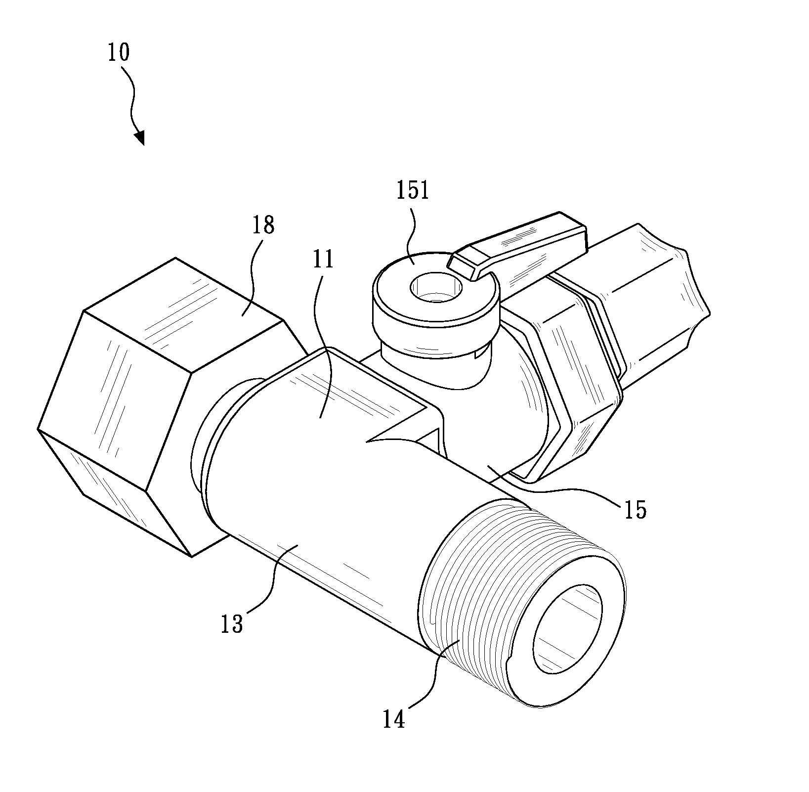
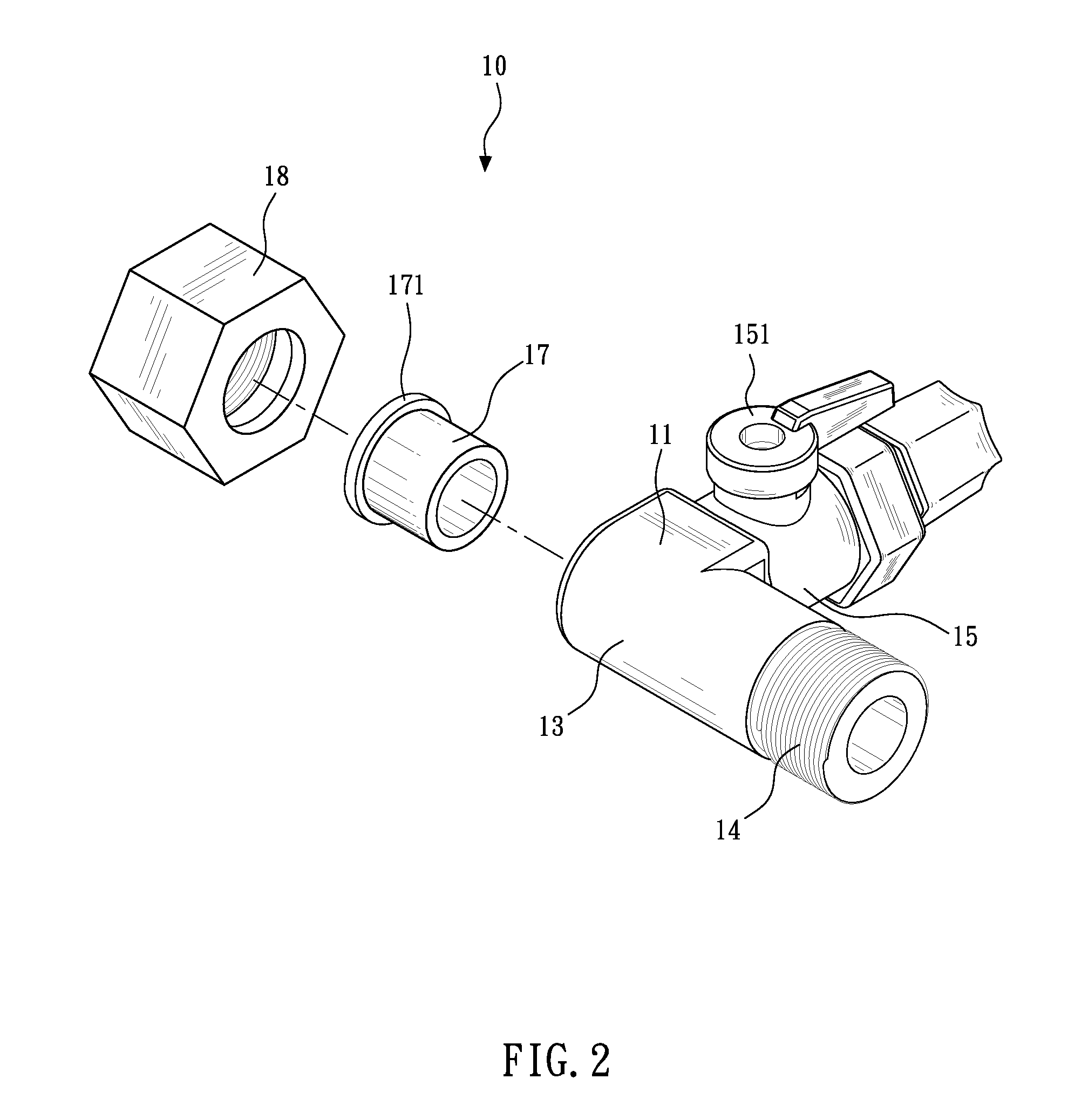
[0016]Referring to FIG. 1 through FIG. 3, a T-shaped valve 10 of the present invention includes a connecting pipe 11. The connecting pipe 11 may be made of plastic or a lead-free metal, and defines therein a channel 12. The connecting pipe 11 has an inlet end provided with an improved fitting structure and an outlet end 14 formed with external threads. The fitting structure is composed of a receiving section 13, an adapter 17 and a nut 18, which ...


PUM


Abstract

A T-shaped valve includes an improved fitting structure is disclosed. A T-shaped valve has a connecting pipe and a branch pipe carrying a control valve. The connecting pipe has an inlet end provided with the fitting structure that includes a receiving section of the connecting pipe defining a receiving portion at the inlet end; an adapter having fixed to the receiving portion and peripherally formed with a flange; and a nut internally formed with a peripheral stepped section for retaining the flange such that the adapter is allowed to rotate with respect to the nut. The T-shaped valve in virtue of the improved fitting structure can be properly installed without repeated adjustment and reinstallation. Furthermore, components of the T-shaped valve are made of alternative material instead of lead-containing metal, so the T-shaped valve ensures water quality.

Description

BACKGROUND OF THE INVENTION[0001]1. Technical Field[0002]The present invention relates to valves, and more particularly to a T-shaped valve equipped with an improved fitting structure that facilitates installation, wherein components of the T-shaped valve are made of plastic instead of metal so as to prevent water flowing therethrough from metal contamination.[0003]2. Description of Related Art[0004]A T-shaped valve conventionally has a connecting pipe ended at two ends with a water inlet and a water outlet, respectively, and a valve portion extending perpendicular to and communicating with the connecting pipe so as to form a T-like shape of the integrated assembly. The water inlet and the water outlet are provided with either internal or external threads by which the water inlet and the water outlet can engage with a water source that supplies water and a extension pipe that leads the water to applications other than that connects the valve portion. In the most common case of insta...

Claims


Application Information

Patent Timeline
Patent Type & Authority Applications(United States)
IPC IPC(8): F16K27/00
CPCF16L41/021F16K27/06
Inventor HUNG, CHIEN-TE
Owner KENT PLASTIC
Why Eureka
Try Eureka