Radar level gauging with detection of moving surface

a technology of moving surface and level gauge, applied in the field of radar level gauge, can solve the problem of not being suitable for applications where power is needed

Active Publication Date: 2013-03-28
ROSEMOUNT TANK RADAR
View PDF19 Cites 28 Cited by
  • Summary
  • Abstract
  • Description
  • Claims
  • Application Information

AI Technical Summary

Benefits of technology

[0019]According to this embodiment, the determination of whether the level is moving or not may thus be based on several pairs of identical pulses, which can make the determination more reliable.

Problems solved by technology

Although highly accurate, classic FMCW systems are relatively power hungry, making them less suitable for applications where power is limited.
During a start up process (when no approximate distance is known) more samples are needed and this is also the case in more complicated cases (turbulence, disturbing echoes etc).

Method used


Image

  • Radar level gauging with detection of moving surface
  • Radar level gauging with detection of moving surface
  • Radar level gauging with detection of moving surface

Examples


Embodiment Construction

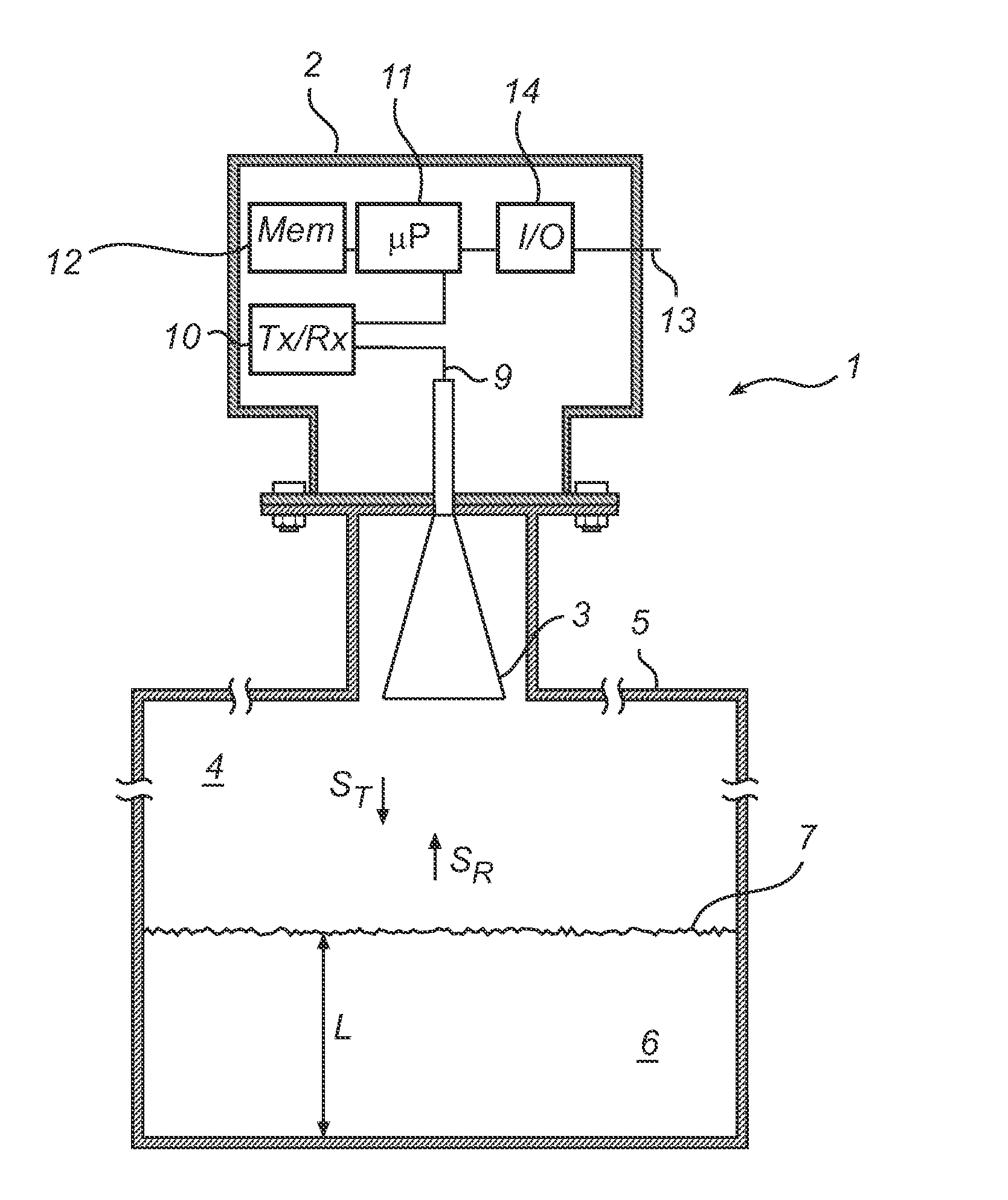
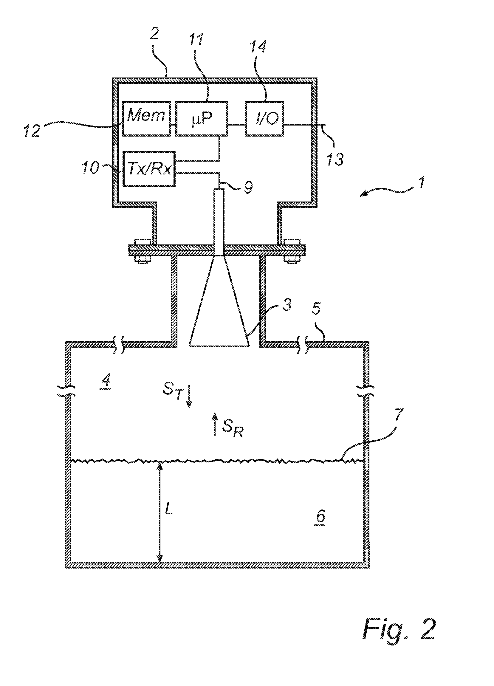
[0029]In the present description, embodiments of the present invention are mainly described with reference to a radar level gauge system having a free propagating antenna for radiating and capturing electromagnetic signals. It should be noted that this by no means limits the scope of the invention, which is equally applicable to other signal propagating devices, including other free propagating antennas such as a rod antenna, a patch antenna, a fixed or movable parabolic antenna or a conical antenna, and wave guides, such as a still pipe, a transmission line or a probe, such as a single-line probe (including a so-called Goubau probe), a twin-line probe or a coaxial probe.

[0030]Further, the operating principle of the level gauge described below is MFPW, as disclosed in U.S. application Ser. No. 12 / 981,995. However, it is realized that the operating principle for performing the level detection may be any kind, including FMCW and pulsed level gauging using time domain reflectometry. As...


PUM


Abstract

A radar level gauging principle including transmitting at least two time separated carrier wave pulses having equal carrier frequencies, determining a change in phase shift associated with two pulses in the transmit signals having equal frequencies, comparing the change with a threshold value, and depending on a result of the comparing step, determining the distance based on a relationship between the transmit signals and the return signals.
By comparing the actual phase resulting from two substantially identical pulses transmitted a certain time apart, an indication of a change of filling level can be obtained. This indication can then be used to initiate a full measurement cycle.

Description

FIELD OF THE INVENTION[0001]The present invention relates to a radar level gauge using electromagnetic waves to determine a distance to a surface of a product in a tank.BACKGROUND OF THE INVENTION[0002]Since the radar level gauging was developed as a commercial product in the 1970's and 1980's, frequency modulated continuous wave (FMCW) has been the dominating measuring principle for high accuracy applications. An FMCW measurement comprises transmitting into the tank a signal which is swept over a frequency range in the order of a few GHz. For example, the signal can be in the range 25-27 GHz, or 9.5-11 GHz. The transmitted signal is reflected by the surface of the contents in the tank (or by any other impedance transition) and an echo signal, which has been delayed a certain time, is returned to the gauge. The echo signal is mixed with the transmitted signal to generate a mixer signal, having a frequency equal to the frequency change of the transmitted signal that has taken place d...

Claims


Application Information

Patent Timeline
Patent Type & Authority Applications(United States)
IPC IPC(8): G01S13/08G01S13/88
CPCG01S13/36G01F23/284
Inventor EDVARDSSON, OLOV
Owner ROSEMOUNT TANK RADAR
Why Eureka
Try Eureka