Battery

a battery and power generating element technology, applied in the field of batteries, can solve the problems of internal short circuit failure and damage to the power generating element itself, and achieve the effects of minimizing the increase in workload, and suppressing the movement of the power generating elemen

Inactive Publication Date: 2013-03-28
GS YUASA INT LTD
View PDF4 Cites 9 Cited by
  • Summary
  • Abstract
  • Description
  • Claims
  • Application Information

AI Technical Summary

Benefits of technology

[0040]According to the first invention, the fixing member used for mounting of the current collector and the electric wiring can be used as it is for the positioning of the spacer for suppressing the movement of the power generating element and the spacer can be used for the positioning of the power generating element in joining the current collector and the power generating element. Therefore, it is possible to suppress the movement of the power generating element in the case of the battery while minimizing the increase in the workload in the assembly process of the battery.
[0041]According to the second invention, the hollow portion in the hollow rivet remaining after the hollow rivet is caulked to fix the current collector to the case is used to carry out the positioning of the spacer and therefore it is possible to appropriately carry out the positioning of the space without requiring special working of the parts.
[0042]According to the third invention, it is possible to suppress the movement of the power generating element both on the positive and negative electrode sides with the single part and therefore it is possible to reduce the number of parts and cost.
[0043]According to the fourth invention, the spacer is formed into the shape of the recessed face to stabilize and appropriately hold the attitude of the power generating element which tries to move to thereby suppress the movement. Therefore, it is possible to more reliably prevent detachment of the power generating element from the current collector.
[0044]According to the fifth invention, it is possible to suppress the bending of the current collector when the vibration or the like is applied to the battery. Therefore, it is possible to more reliably protect the joined state of the current collector and the power generating element to each other.
[0045]According to the sixth invention, it is possible to suppress the movement of the power generating element in the case of the battery irrespective of the use situation of the battery.

Problems solved by technology

The force acting on the joints between the power generating element and the current collectors may separate them from each other or damage the power generating element itself.
Furthermore, if the power generating element is displaced to come in contact with current paths from the electrode terminals to the current collectors, a resin separator included in the power generating element contracts due to heat generation when high current is applied, which causes an internal short circuit failure.

Method used


Image

  • Battery
  • Battery
  • Battery

Examples


Embodiment Construction

[0054]Embodiments of a battery according to the present invention will be described below based on the drawings.

[0055]In each of the embodiments, a nonaqueous electrolyte secondary battery (more specifically, a lithium ion battery) which is an example of a secondary battery will be described as the battery.

[Structure of Nonaqueous Electrolyte Secondary Battery RB]

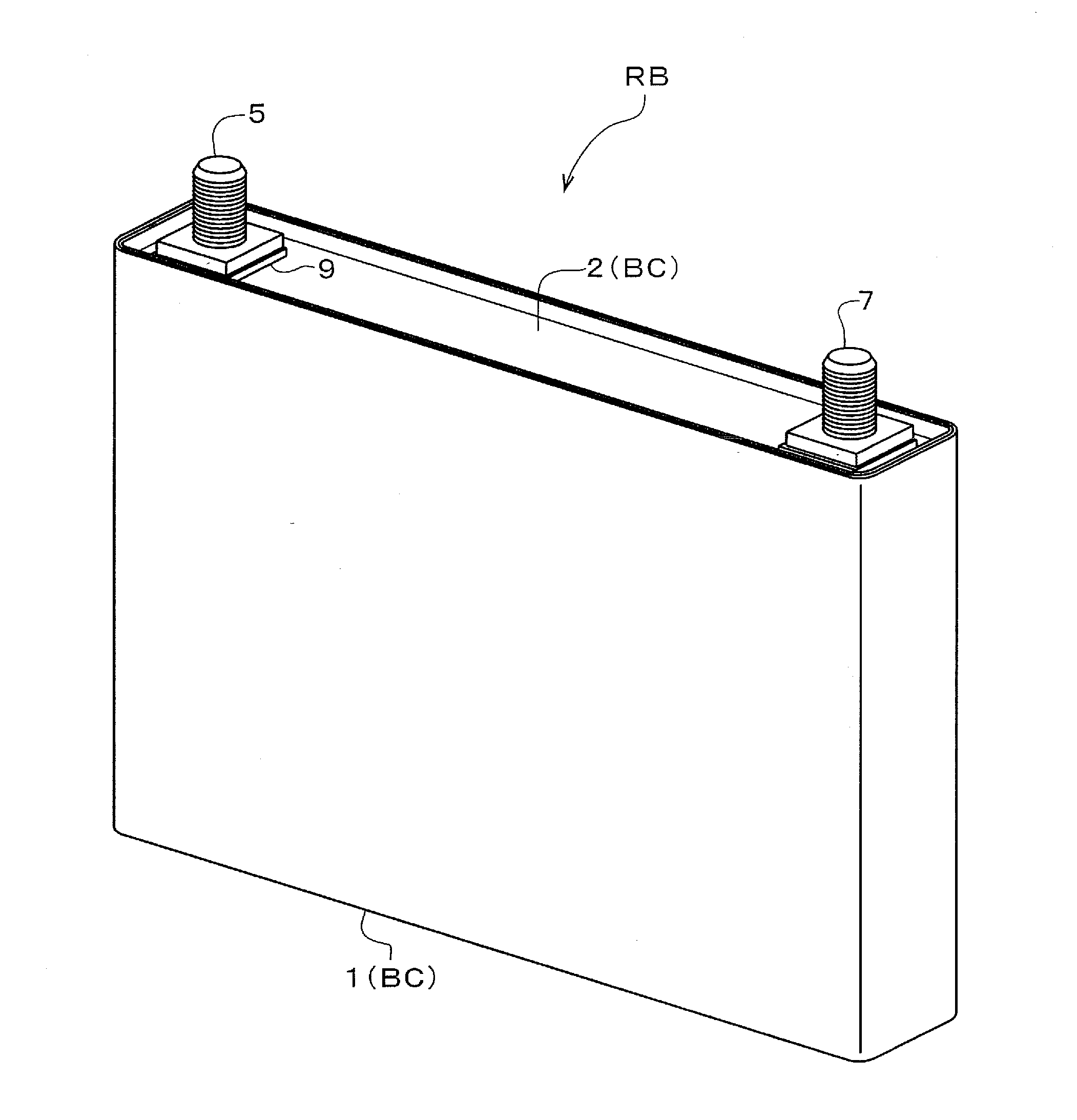
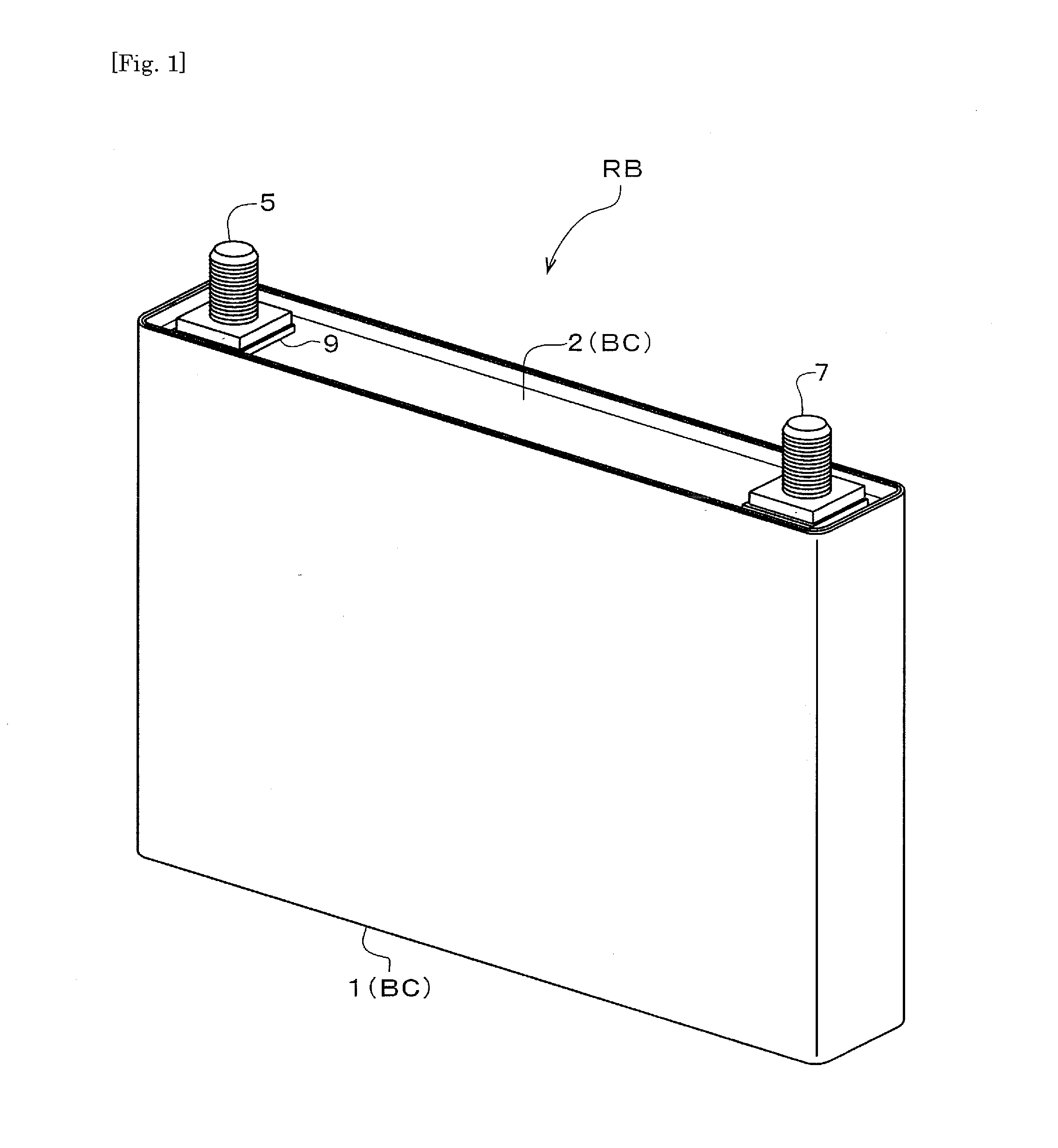
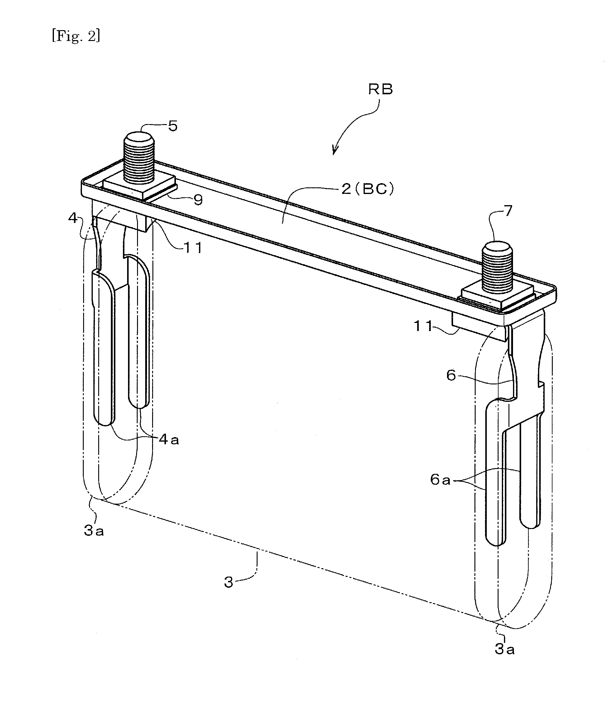
[0056]As shown in perspective views in FIGS. 1 and 2 and a front view in FIG. 4, the nonaqueous electrolyte secondary battery RB in the embodiment has a case BC formed by placing and welding a lid portion 2 onto an open face of a can body 1 in a cylindrical shape with a bottom (more concretely, a rectangular cylindrical shape with a bottom). The lid portion 2 is formed into a shallow plate shape by bending, at a right angle, an end edge portion of a strip-shaped rectangular plate member throughout an entire periphery and a terminal bolt 5 which is a positive electrode terminal and a terminal bolt 7 which is a negative elect...


PUM

PropertyMeasurementUnit
electric conductivityaaaaaaaaaa
shapeaaaaaaaaaa
forceaaaaaaaaaa

Abstract

The present invention suppresses movement of a power generating element in a case of a battery while minimizing an increase in a workload in an assembly process of the battery.
In the battery including: a power generating element 3; a case BC housing the power generating element 3; an electrode terminal 5 disposed outside the case; a current collector 4 connected to the power generating element 3; and a fixing member FE for fixing the current collector 4 to the case BC and having electric conductivity, the current collector 4 and the fixing member FE forming an energizing path between the power generating element 3 and the electrode terminal 5, a spacer 11 which is positioned by engagement with the fixing member FE and which suppresses movement of the power generating element 3 is disposed between the fixing member FE and the power generating element 3.

Description

TECHNICAL FIELD[0001]The present invention relates to a battery including a power generating element, a case housing the power generating element, an electrode terminal disposed outside the case, a current collector connected to the power generating element, and a fixing member for fixing the current collector to the case and having electric conductivity. The current collector and the fixing member form an energizing path between the power generating element and the electrode terminal.BACKGROUND ART[0002]A basic structure of the battery includes a power generating element housed in a case of the battery and current collectors for electrically connecting the power generating element and the electrode terminals mounted to the case.[0003]As a general structure, the current collectors and the power generating element are connected by welding or the like and the current collectors are fixed to the case by fixing members such as rivets and are electrically connected to the electrode termi...

Claims


Application Information

Patent Timeline
Patent Type & Authority Applications(United States)
IPC IPC(8): H01M2/30H01M4/00H01M50/528H01M50/533H01M50/538H01M50/55H01M50/553H01M50/564
CPCH01M2/0217H01M2/22H01M4/00H01M2/30H01M2/263Y02E60/10H01M50/103H01M50/538H01M50/528Y02P70/50H01M50/564H01M50/55H01M50/553H01M50/533
Inventor SASAKI, TAKESHIMORI, SUMIOTESHIMA, MINORUYAMAFUKU, TARO
Owner GS YUASA INT LTD
Why Eureka
Try Eureka