
Terminal fitting

a technology of fittings and fittings, applied in the direction of coupling contact parts, coupling device connections, electrical devices, etc., can solve the problems of relative high cost, achieve the effect of improving the reliability of the contact function, preventing the improper deformation of the resilient contact piece, and increasing the contact pressur

Inactive Publication Date: 2013-03-28
SUMITOMO WIRING SYST LTD
View PDF67 Cites 18 Cited by
  • Summary
  • Abstract
  • Description
  • Claims
  • Application Information

AI Technical Summary

Benefits of technology

The patent text describes a terminal fitting design that reduces the cost of materials and improves the reliability of the contact function by using a resilient contact piece. The design uses an inexpensive material for the shell and a costly material for the terminal main body. By using an exclusive fitting portion on the shell, the size of the shell can be reduced and the material cost of the terminal main body can be reduced compared to a design that uses a fitting portion that extends over the entire shell. The design also includes at least one restricting portion on the shell to prevent improper deformation of the resilient contact piece. Overall, the design improves the cost-effectiveness and reliability of the terminal fitting.

Problems solved by technology

An electrically conductive material, such as copper alloy, needs to be used as the material of the terminal main body formed with the at least one resilient contact piece, despite the relatively high cost.

Method used


Image

  • Terminal fitting
  • Terminal fitting
  • Terminal fitting

Examples


first embodiment

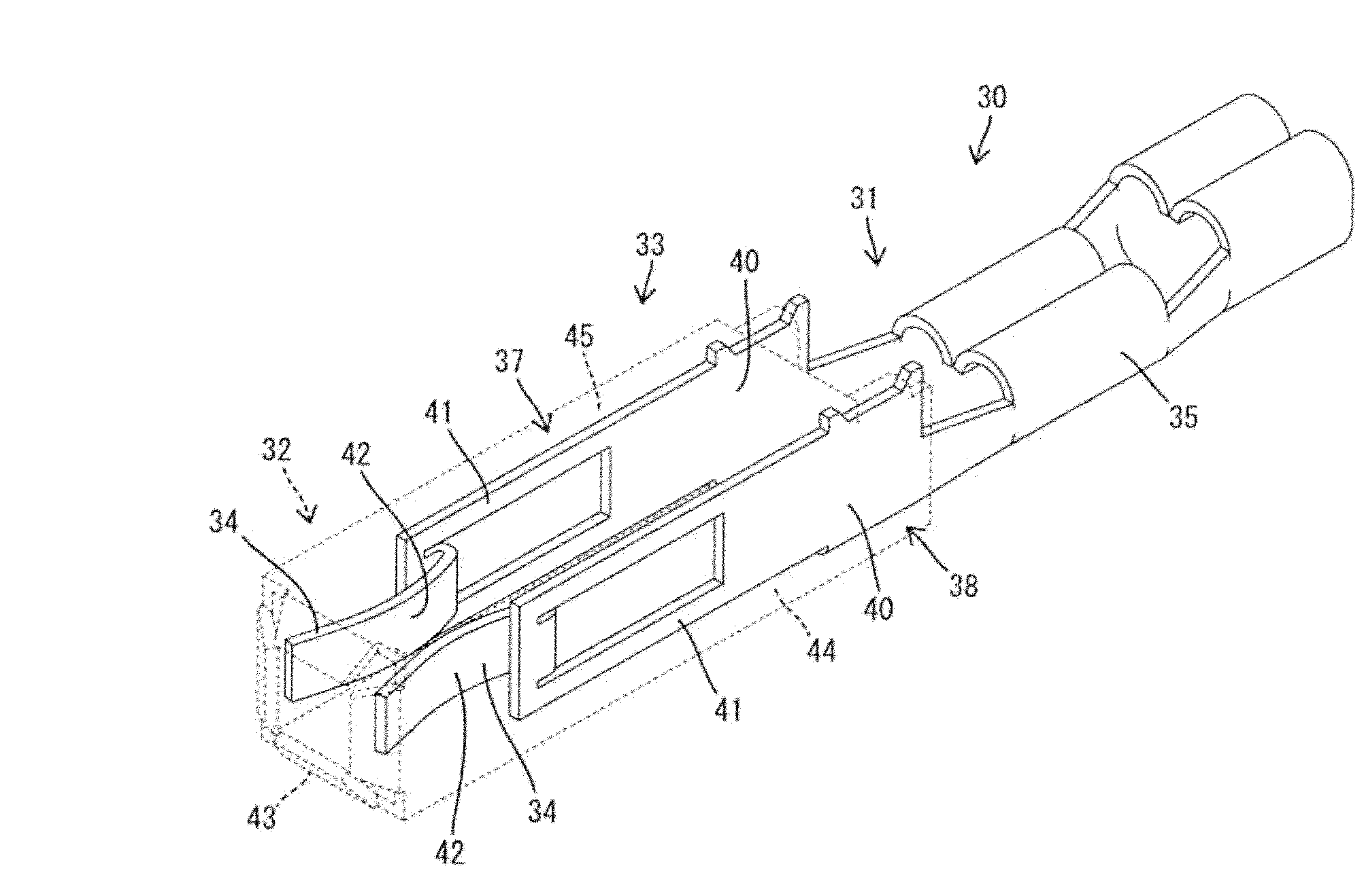
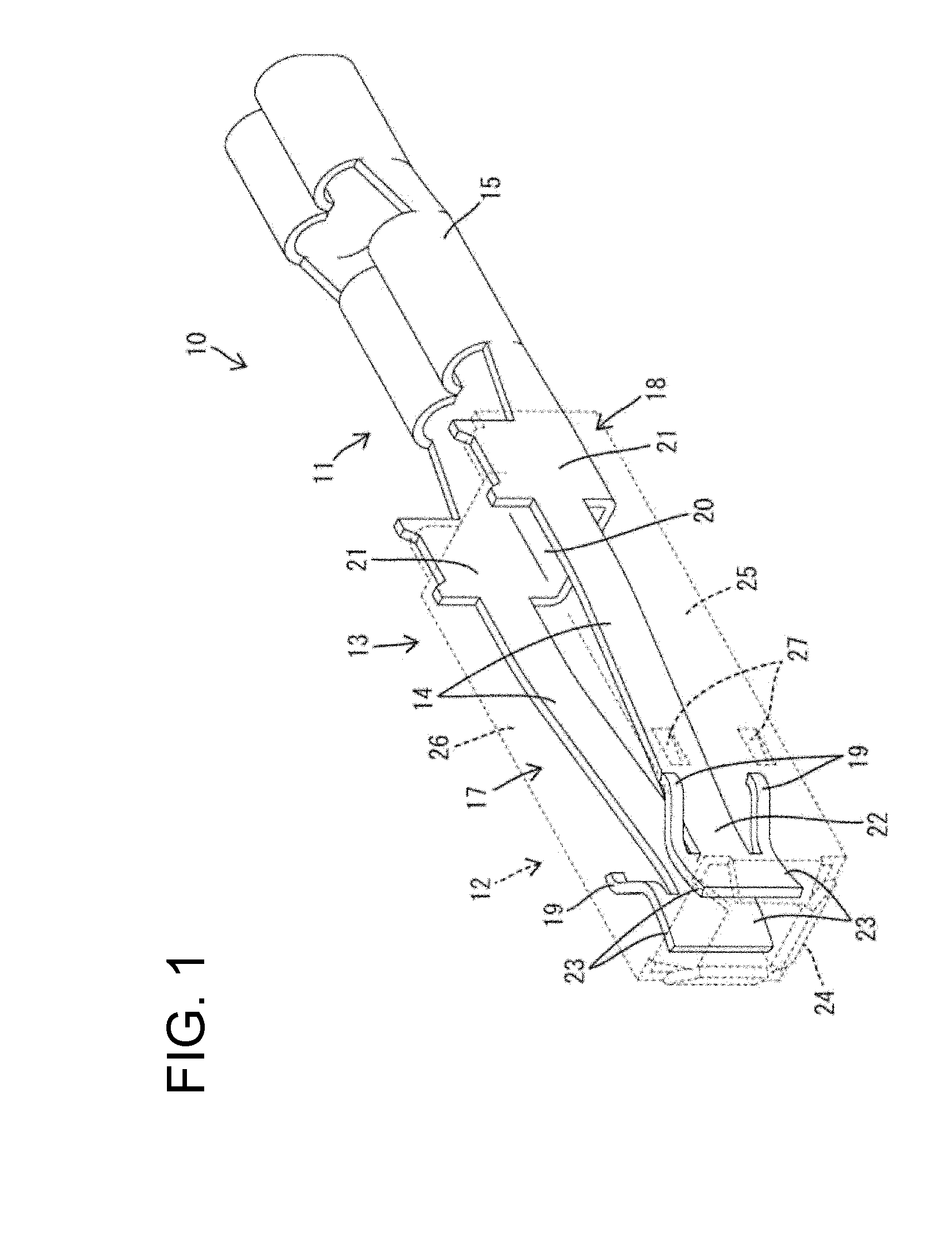
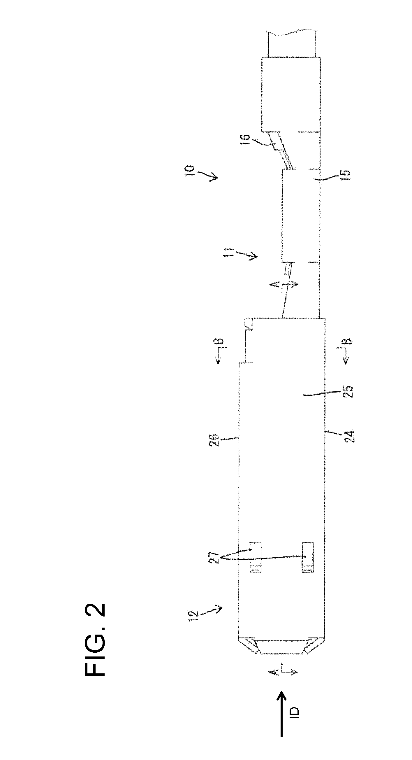
[0027]the invention is described with reference to FIGS. 1 to 5. A terminal fitting 10 of the first embodiment is long and narrow in forward and backward directions and includes a terminal main body 11 and a shell 12 that are components separate from each other as shown in FIGS. 1 to 4. The terminal main body 11 is made of copper alloy, and the shell 12 is made of a material different from the terminal main body 11, such as stainless steel or an inexpensive material other than stainless steel. A rectangular tube 13 is formed at a front area of the terminal fitting 10 in forward and can receive a tab 29 of a male terminal inserted from the front along an insertion direction ID. As shown in FIGS. 1, 3 and 4, two resilient contact pieces 14 are accommodated in the rectangular tube 13 and can be brought resiliently into contact with the tab 29. A wire crimping portion 15 in the form of at least one open barrel is formed in a rear area of the terminal fitting 10 and can be crimped, bent ...

second embodiment

[0053]The fitting portion is arranged at the rear of the shell, the plates extend forward from the fitting portion and the resilient contact pieces are turned forward from the plates in the However, the fitting portion may be arranged at the front end part of the shell, the plates may extend back from the fitting portion and the resilient contact pieces may be turned back from the plates.

[0054]In the second embodiment, the configuration of the first embodiment that two resilient pieces extend from the substantially opposite side edges of the resilient contact pieces may also be applied.


PUM


Abstract

A terminal fitting (10) includes a terminal main body (11) and a shell (12), which is a component separate from the terminal main body (11). The terminal main body (11) has a fitting portion (18) and resilient contact pieces (14). The shell (12) is a rectangular tube engaged with the fitting portion (18) of the terminal main body (11) and surrounding the resilient contact pieces (14). Even though being relatively expensive, an electrically conductive material such as copper alloy needs to be used as the material of the terminal main body (11) formed with the resilient contact pieces (14). However, an inexpensive material can be used for the shell (12) since electrical conductivity is not required. Therefore, cost can be reduced as compared with the case where a terminal fitting is made entirely of an expensive electrically conductive material.

Description

BACKGROUND OF THE INVENTION[0001]1. Field of the Invention[0002]The invention relates to a terminal fitting.[0003]2. Description of the Related Art[0004]U.S. Pat. No. 5,947,777 discloses a female terminal fitting with resilient contact piece accommodated in a rectangular tube. A tab of a mating male terminal is inserted into the rectangular tube and presses the resilient contact piece. As a result, the resilient contact piece is deformed and the tab is sandwiched resiliently between the resilient contact piece and a wall of the rectangular tube. The rectangular tube ensures a contact pressure between the tab and the resilient contact piece and also protects the resilient contact piece by surrounding it.[0005]The above-described terminal fitting, including the rectangular tube and the resilient contact piece, is formed from a single piece of an electrically conductive copper alloy. The copper alloy, however, is relatively expensive and leads to a high production cost for the terminal...

Claims


Application Information

Patent Timeline
Patent Type & Authority Applications(United States)
IPC IPC(8): H01R11/22
CPCH01R4/185H01R13/20H01R13/114
Inventor ITOU, TOMOYAIIHOSHI, SHINJI
Owner SUMITOMO WIRING SYST LTD
Features
  • Generate Ideas
  • Intellectual Property
  • Life Sciences
  • Materials
  • Tech Scout
  • Unparalleled Data Quality
  • Higher Quality Content
  • 60% Fewer Hallucinations
Learn More