Electric motorcycle

a technology for electric motorcycles and motorcycles, applied in the direction of electric propulsion mountings, electric devices, cycles, etc., can solve the problems of increasing length in the fore-and-aft direction, and achieve the effect of reducing the dimension simple configuration, and easy keeping of the weight balance of the power unit in the vehicle width direction

Active Publication Date: 2013-04-04
HONDA MOTOR CO LTD
View PDF7 Cites 26 Cited by
  • Summary
  • Abstract
  • Description
  • Claims
  • Application Information

AI Technical Summary

Benefits of technology

[0008]In order to achieve the above-described object, there is provided an electric motorcycle including: a power unit including a motor whose revolving shaft is oriented in the vehicle width direction and a centrifugal clutch configured to transmit a rotary drive force of the motor to an output shaft provided in parallel to the revolving shaft. The centrifugal clutch is coaxially arranged with the motor, and includes a primary driven gear arranged coaxially with the output shaft and is configured to transmit a drive force transmitted from the centrifugal clutch to the output shaft, and the primary driven gear is disposed so as to be interposed between the centrifugal clutch and the motor in the axial direction of the revolving shaft. Therefore, the primary driven gear can be disposed by effectively using a space between the centrifugal clutch and the motor, and hence the dimension of the power unit in the vehicle width direction can be significantly reduced.
[0009]In further accordance with the present invention, a clutch plate configured to hold a clutch shoe of the centrifugal clutch is fixed to one end portion of the revolving shaft, a bottomed cylindrical shaped clutch outer that constitutes the centrifugal clutch is disposed at a position closer to the motor with respect to the clutch plate, the clutch outer is fixed to a clutch outer holder, which is relatively rotatable with respect to the revolving shaft, and the primary driven gear engages a primary drive gear formed on an outer peripheral portion of the clutch outer holder. Therefore, the power unit and a power transmitting system can be configured with a simple configuration.
[0011]In further accordance with the present invention, the output shaft is disposed so that one end portion thereof projects outward of the vehicle from the power unit on the back side of the centrifugal clutch with respect to the vehicle body, and a drive sprocket on which a drive chain is to be wound is fixed to the one end portion of the output shaft. Therefore, the power transmission from the power unit to the drive wheel can be achieved with a simple configuration.
[0012]In further accordance with the present invention, the output shaft is supported by two bearings disposed apart from each other, and the bearing on the side proximity to the drive sprocket, which is one of the two bearings, is disposed radially outward of the centrifugal clutch. Therefore, while avoiding interference between the centrifugal clutch and the drive sprocket, the drive sprocket can be put inward toward the center side of the case and hence the dimension of the power unit in the vehicle width direction can be reduced.
[0013]In further accordance with the present invention, the primary drive gear and the primary driven gear are disposed on a vehicle body centerline of the electric motorcycle. As a result, the weight balance of the power unit in the vehicle width direction can easily be kept and proper weight balance in the vehicle width direction of the electric motorcycle can easily be ensured.
[0014]In further accordance with the present invention, a power unit has a configuration in which a clutch case is mounted on one side of a case in the vehicle width direction, a motor cover is mounted on the other side, the revolving shaft is supported by a bearing fitted to the case and a bearing fitted to the motor cover, and the output shaft is supported by the bearing fitted to the case and the bearing fitted to the clutch case. Therefore, the power unit which supports the two axes efficiently using a plurality of the cases and the cover member is achieved.

Problems solved by technology

However, since the motor and the centrifugal clutch are arranged in the fore-and-aft direction of the vehicle, there arises a problem that the length in the fore-and-aft direction tends to increase.

Method used


Image

  • Electric motorcycle
  • Electric motorcycle
  • Electric motorcycle

Examples


Embodiment Construction

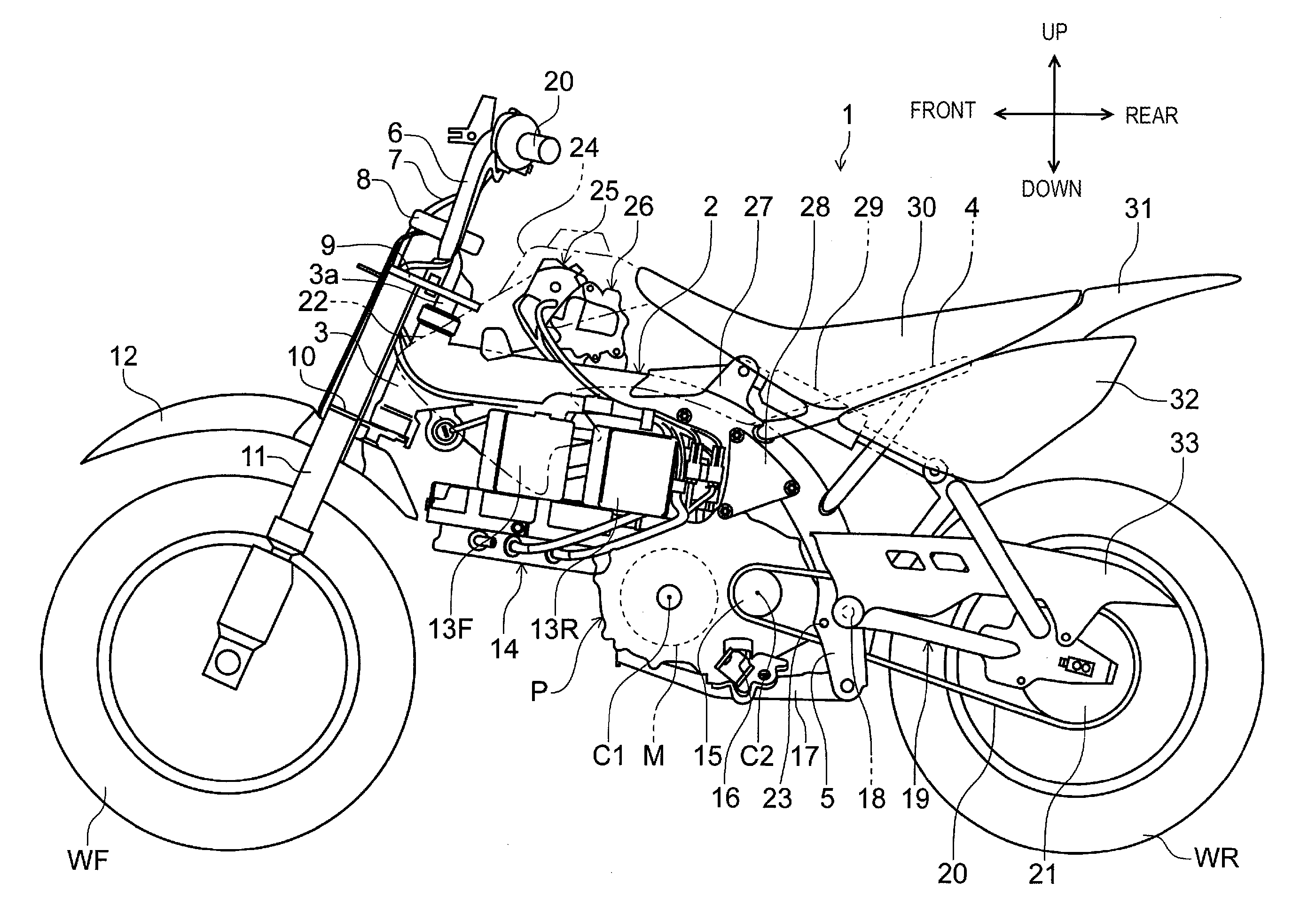
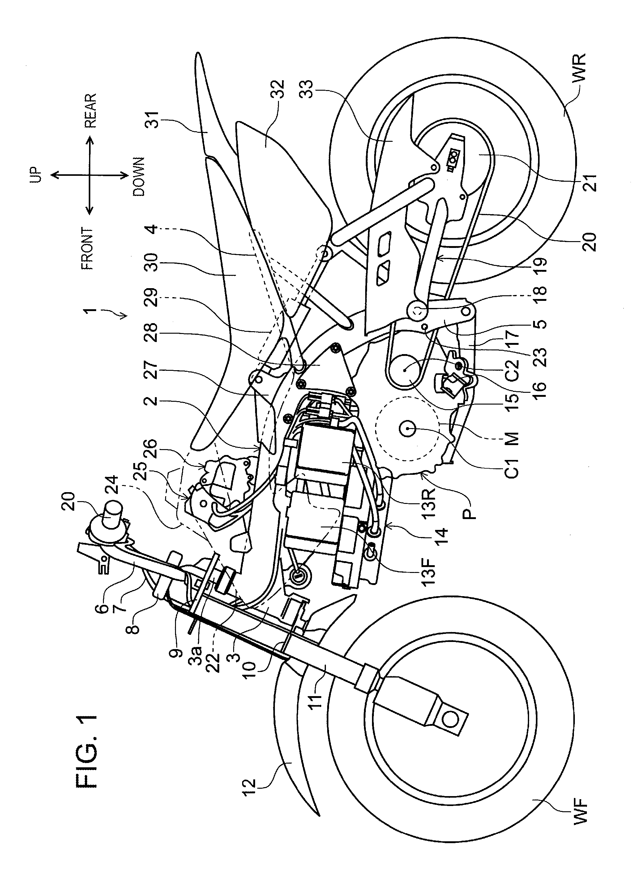
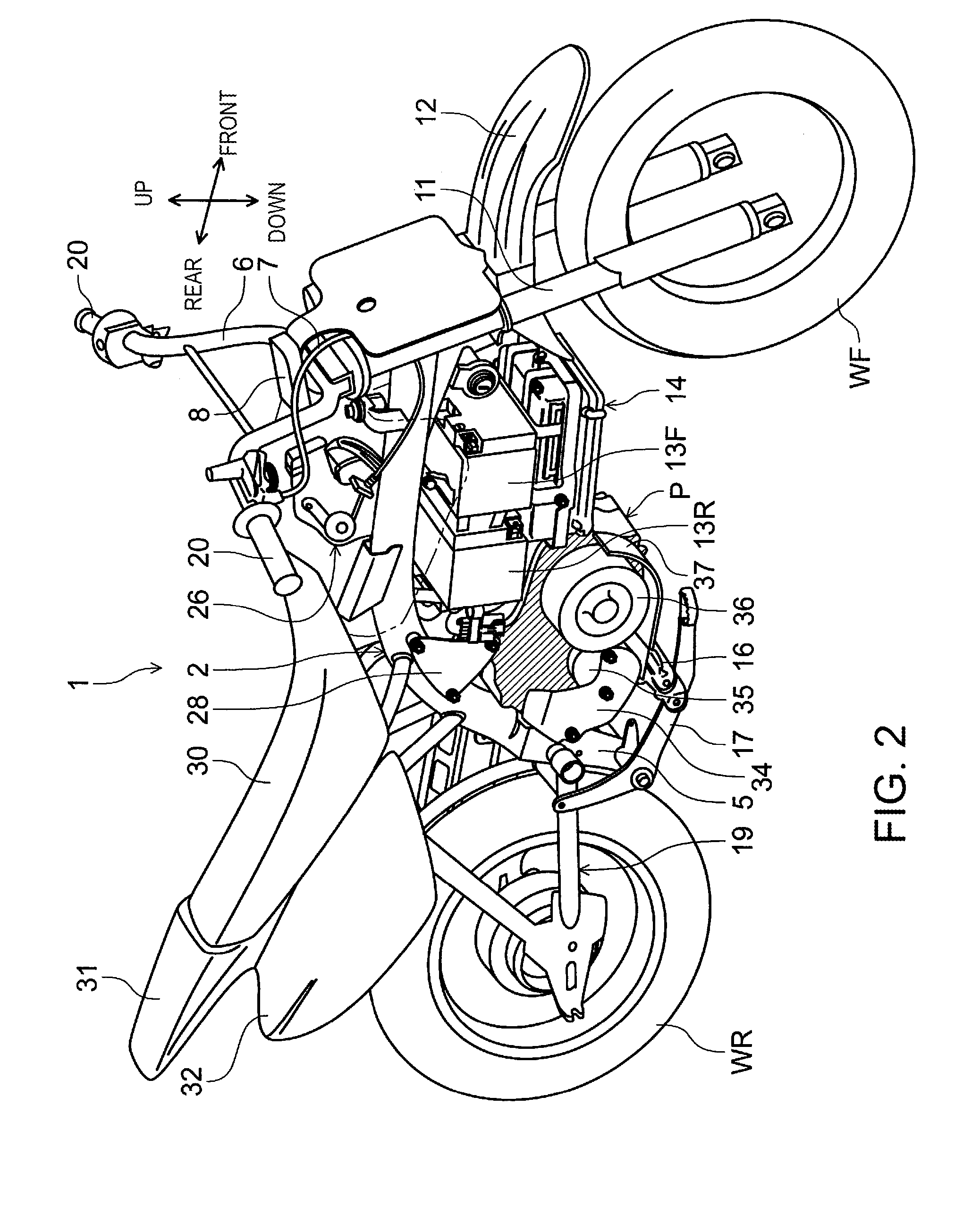
[0025]Referring now to the drawings, preferred embodiments of the invention will be described. FIG. 1 is a left side view of an electric motorcycle 1 according to an embodiment of the present invention. FIG. 2 is a perspective view of the electric motorcycle 1. The electric motorcycle 1 has a configuration in which a power unit P including a motor M, a decelerating mechanism and the like is mounted on a vehicle body frame 2, and a rotary drive force generated by the power unit P is transmitted to a rear wheel WR via a chain-drive mechanism.

[0026]A head pipe 3 configured to axially support a stem shaft 3a so as to be rotatable is coupled to a front end of the vehicle body frame 2 of the electric motorcycle 1. A sheet frame 4 is coupled to the vehicle body frame 2 extending rearward from the head pipe 3 at a portion curved downward of the vehicle body, and left and right pivot plates 5 are coupled to the lower side thereof. A pivot shaft 18 configured to axially support a swing arm 19...


PUM


Abstract

In a electric motorcycle including a power unit having a motor whose revolving shaft is oriented in the vehicle width direction, and a centrifugal clutch configured to transmit a rotary drive force of the motor to an output shaft, the centrifugal clutch is arrange coaxially with the motor. A primary driven gear arranged coaxially with the output shaft and configured to transmit a drive force transmitted from the centrifugal clutch to the output shaft is provided. The primary driven gear is arranged so as to be interposed between the centrifugal clutch and the motor in the axial direction of the revolving shaft. A clutch outer is fixed to a clutch outer holder which is relatively rotatable with respect to the revolving shaft, and the primary driven gear is engaged with a primary drive gear formed on the outer periphery of the clutch outer holder.

Description

BACKGROUND OF THE INVENTION[0001]1. Field of the Invention[0002]The present invention relates to an electric motorcycle and, more specifically, to an electric motorcycle configured to travel by driving a motor with power supplied from a battery.[0003]2. Description of Related Art[0004]In the related art, the electric motorcycle including a motor-integrated power unit mounted on a vehicle body frame, and configured to travel by transmitting a rotary drive force of the motor to a drive wheel is known.[0005]For example, in Japanese Patent No. 2988993 an electric motorcycle including a rear wheel as a drive wheel is mounted at a rear end of a swing arm axially supported by the vehicle body frame so as to be swingable, and is configured to transmit a rotary drive force of a motor in a power unit to the rear wheel via a chain-drive mechanism. Stored in the interior of the power unit are the motor as a power source, a continuously variable transmission having a V-belt entrained about a dri...

Claims


Application Information

Patent Timeline
Patent Type & Authority Applications(United States)
IPC IPC(8): B62K11/00
CPCB62M7/04B62K2208/00B62K2204/00B62K11/04B60L15/2054B60L2200/12B60L2240/507B60L2220/50Y02T10/72B60L50/20Y02T10/64
Inventor ISHIKAWA, JUNNISHIMORI, HIROYUKINAKAZAWA, TAKEOTOKITO, AKIRA
Owner HONDA MOTOR CO LTD
Why Eureka
Try Eureka