System and method for wireless heat detection

Active Publication Date: 2013-04-04
JOHNSON CONTROLS TYCO IP HLDG LLP
View PDF8 Cites 7 Cited by
  • Summary
  • Abstract
  • Description
  • Claims
  • Application Information

AI Technical Summary

Benefits of technology

The patent describes a system and method for monitoring heat conditions in a building to check if its structural elements are safe from heat-related damage. The system is affordable and easy to install, and it can provide real-time monitoring of heat conditions. Its technical effect is to help ensure the safety of building structural elements.

Problems solved by technology

However, the personal protective equipment may not provide a firefighter with adequate protection when the firefighter is exposed to a structural failure within a building.
In some cases, structural failures can trap the firefighter within a building and / or can seal off potential exit paths.
Such physical observations, however, may be unreliable and are often limited by the physical signs that are visible to the firefighters.
As a result, firefighters may lack knowledge of a potential structural failure which may result in the firefighter being injured, or to run out of air after becoming entangled or disoriented as an indirect result of a structural collapse.
Such sensors are expensive, however, which limits their widespread application.
In addition, the size and wiring required for such head sensors may make it impractical to install such sensors on trusses, cross-members, and beams in sufficient quantity to detect when dangerous heat impinges on the structural members.
Battery powered sensors may be used for applications in which it is impractical to use wired sensors (due to the presence of moving parts which make it difficult to maintain electrical connections).
Current battery operated devices may also be undesirable, however, because batteries typically require replacement at periodic time intervals (6 months, 1 year).
Even for cases in which a battery may last extended periods (up to 7+ years) current battery powered devices still can be undesirable because the sensor may be disposed in a location that is difficult to access in order to change the battery.

Method used


Image

  • System and method for wireless heat detection
  • System and method for wireless heat detection
  • System and method for wireless heat detection

Examples


Embodiment Construction

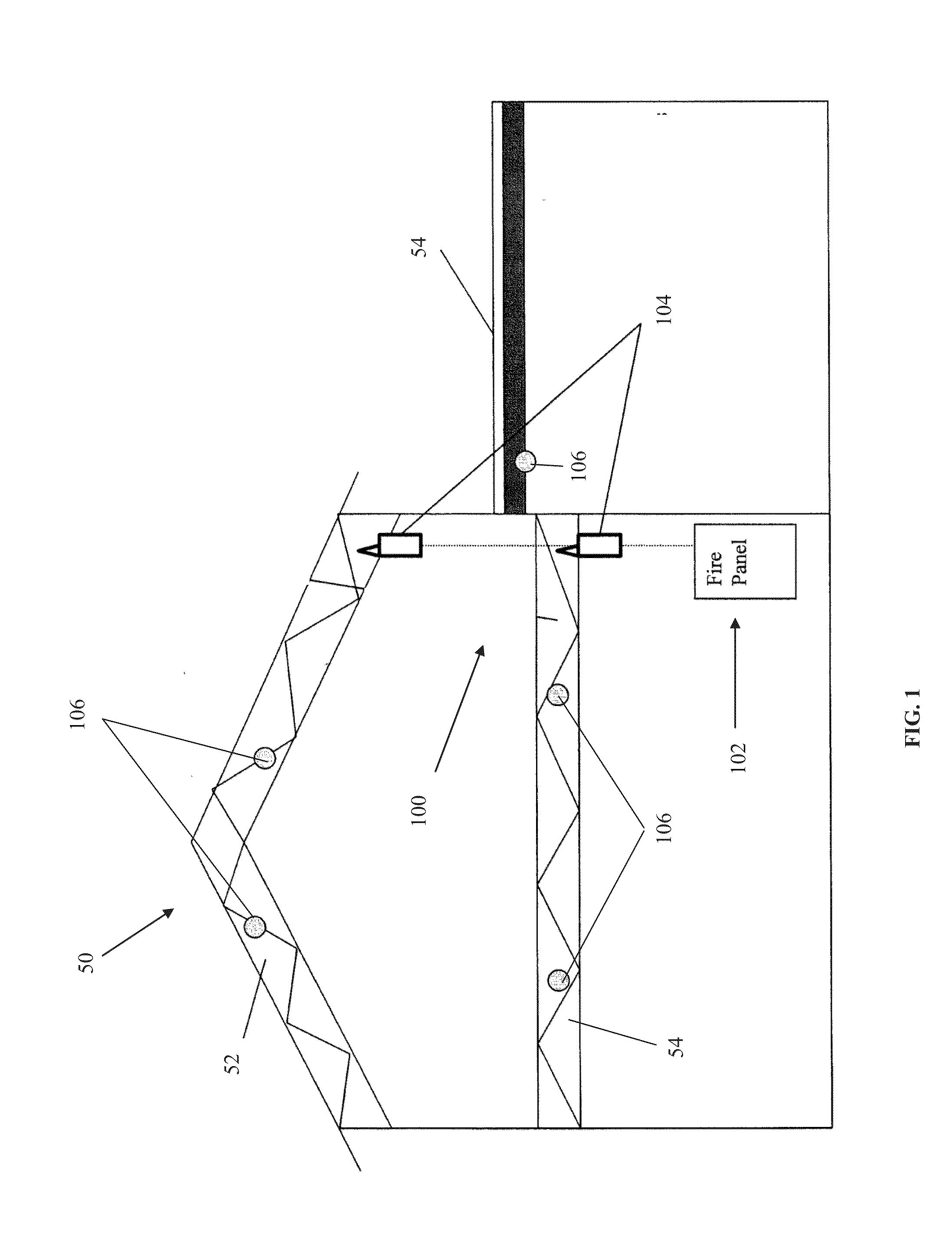
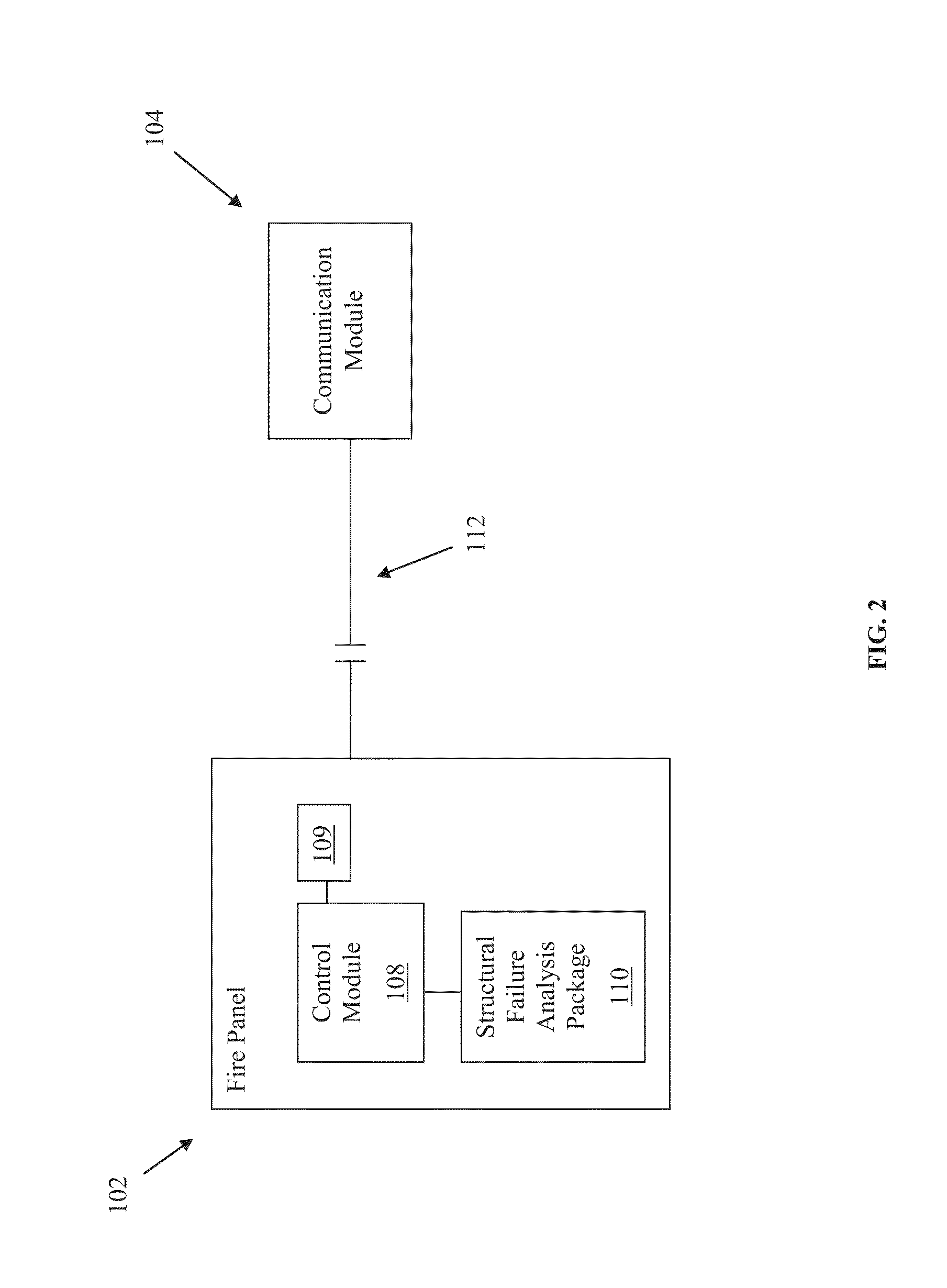
[0019]A system and method are disclosed for enabling early detection of fires in buildings. The system and method can also be used to detect high heat conditions that occur prior to a fire condition (i.e., prior to ignition temperature of an associated structure). The system and method can further be used to predict failure of structural members in buildings that are subject to high heat conditions during a fire. A plurality of sensors can be disposed at a variety of locations on building structural members. The sensors may be configured to convert energy from heat (i.e., fire) to wireless signals that can be received by an antenna associated with a communication module. The antenna and communication module can transmit the received information to a fire panel, which notifies operators and building occupants that structural elements of a building are being subjected to high heat conditions.

[0020]FIG. 1 shows a building 50 including an exemplary alert system 100. Generally, the syste...


PUM


Abstract

A system for wireless heat detection is disclosed. The system includes one or more heat sensors that convert sensed heat energy into electrical power for transmitting an alarm signals. A remote system may trigger an alarm based on the received alarm signals. The heat sensors may be placed at discrete locations within an interior of a building to monitor a condition of the infrastructure of the building. The remote system can include a communications module for receiving the signal and transmitting an alarm signal to an associated fire panel. The fire panel may analyze the signal, as well as signals generated from adjacent sensors, to determine whether a fire condition exists within a building. Appropriate notification devices may then be activated based on the determination. Other embodiments are disclosed and claimed.

Description

FIELD OF THE DISCLOSURE[0001]This invention relates generally to systems and methods for sensing heat from objects or equipment, and more particularly to a system and method for detecting abnormal heat conditions in buildings.BACKGROUND OF THE DISCLOSURE[0002]Advancements in personal protective equipment (PPE) have enabled firefighters to operate and survive in relatively extreme conditions when fighting fires within a building. However, the personal protective equipment may not provide a firefighter with adequate protection when the firefighter is exposed to a structural failure within a building. In some cases, structural failures can trap the firefighter within a building and / or can seal off potential exit paths.[0003]To determine if a building is becoming unstable, firefighters generally use a variety of physical observations. For example, firefighters may rely on physical observations of the building such as observing bowed walls or feeling for softness in a floor area. Such ph...

Claims


Application Information

Patent Timeline
IPC IPC(8): G08B1/08G01K1/02
CPCG08B17/06G08B25/10G01K2215/00G01K3/005G01K1/024
Inventor FARLEY, DANIEL G.RASBAND, PAUL B.
Owner JOHNSON CONTROLS TYCO IP HLDG LLP
Why Eureka
Try Eureka