Eureka AIR delivers breakthrough ideas for toughest innovation challenges, trusted by R&D personnel around the world.

Imaging apparatus, computer readable medium and imaging method

Active Publication Date: 2013-04-04
FUJIFILM CORP
View PDF5 Cites 3 Cited by
  • Summary
  • Abstract
  • Description
  • Claims
  • Application Information

AI Technical Summary

Benefits of technology

This patent is about an imaging apparatus or method that reduces noise in image signals. It does this by controlling the pulse width of synchronization signals sent to the imaging device, which allows for longer periods of feed-through and signaling during pixel addition in the horizontal direction. The method also performs noise reduction processing that uses the feed-through and signaling periods to reduce effects of noise in the image signals. By calculating a pixel value based on signals sampled in both the feed-through and signaling periods, the method achieves improved signal-to-noise ratios. Overall, this patent provides a technical solution for improving the quality of still and video images.

Problems solved by technology

If a low-speed A / D converter is used, the frame rate decreases and low frequency noise (for example, 1 / f noise) becomes obvious.

Method used


Image

  • Imaging apparatus, computer readable medium and imaging method
  • Imaging apparatus, computer readable medium and imaging method
  • Imaging apparatus, computer readable medium and imaging method

Examples


Embodiment Construction

[0022]Herebelow, an exemplary embodiment of the present invention is described with reference to the attached drawings.

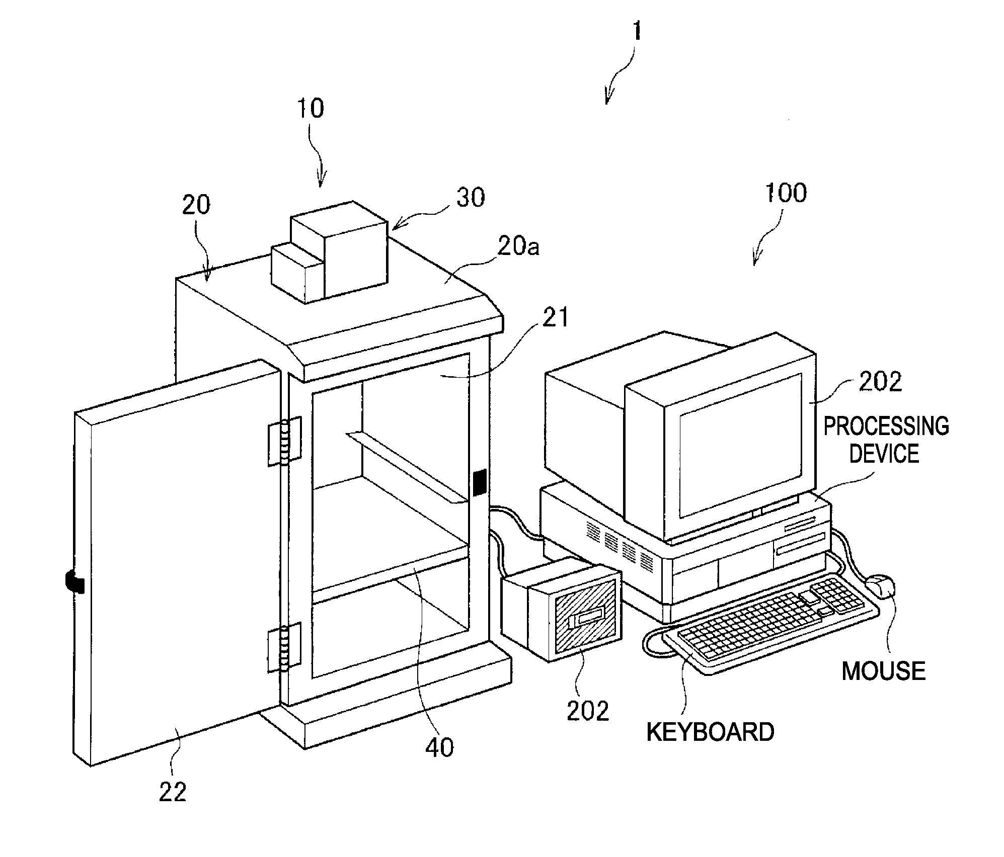
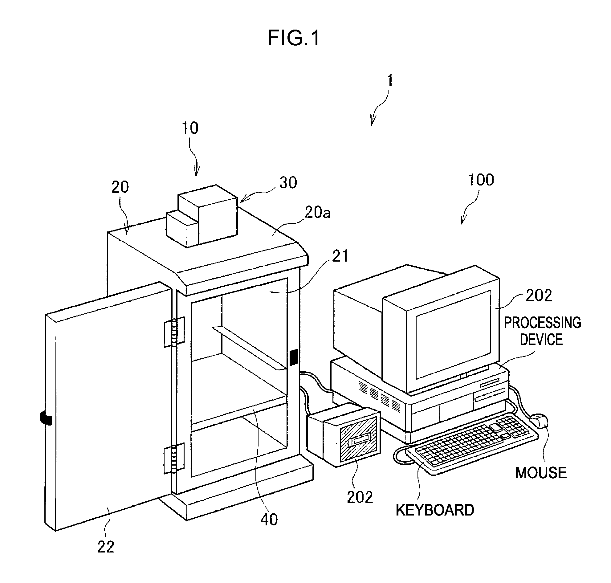
[0023]FIG. 1 is a perspective diagram showing an example of an imaging system that utilizes an imaging apparatus relating to the present invention. The imaging system is an imaging system 1 that images an imaging subject by illuminating excitation light / not illuminating excitation light in accordance with the imaging subject and acquires a captured image of the imaging subject. The imaging system 1 includes an imaging apparatus 10 and an image processing device 100.

[0024]The imaging apparatus 10 images the imaging subject and outputs the acquired image data of the imaging subject to the image processing device 100. The image processing device 100 applies predetermined image processing to the received image data in accordance with requirements, and displays the image data at a display section 202.

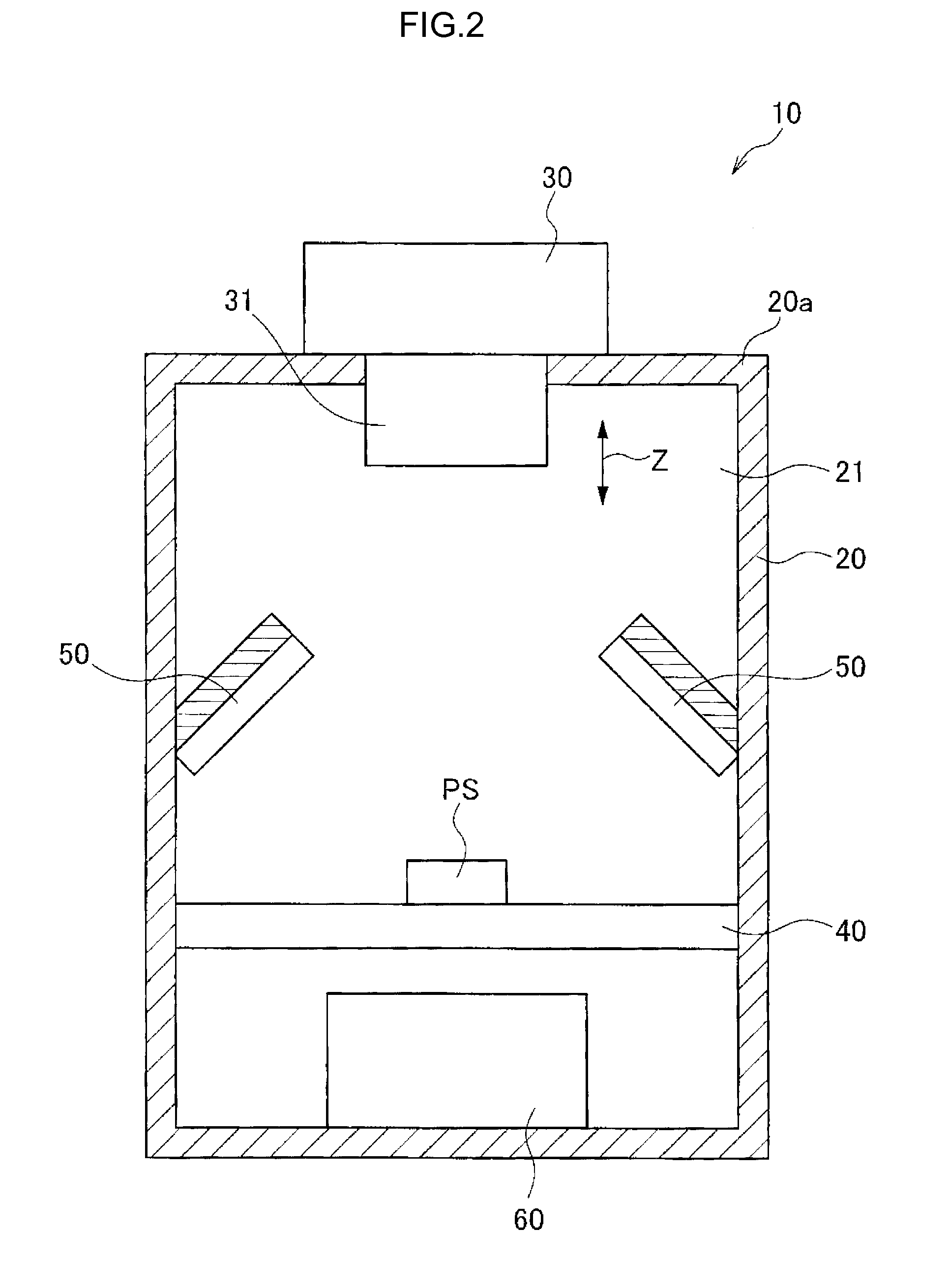
[0025]FIG. 2 shows a front elevation diagram of the imaging apparatus 1...


PUM


Abstract

An imaging apparatus is provided with a control unit, a noise reduction processing unit and a pixel value calculation unit. The control unit controls pulse widths of horizontal synchronization signals outputted to an imaging device such that a feed-through period and a signal period, in a case in which pixel addition in the horizontal direction is performed at the imaging device and imaging signals are outputted, are longer than a feed-through period and a signal period, in a case in which pixel addition in the horizontal direction is not performed at the imaging device. The noise reduction processing unit executes noise reduction processing to reduce the effects of noise produced in the imaging signals. The pixel value calculation unit calculates a pixel value on the basis of a first signal sampled in the feed-through period and a second signal sampled in the signal period.

Description

CROSS-REFERENCE TO RELATED APPLICATIONS[0001]This application claims priority under 35 USC 119 from Japanese Patent Application No. 2011-214705 filed on Sep. 29, 2011, the disclosure of which is incorporated by reference herein.BACKGROUND OF THE INVENTION[0002]1. Field of the Invention[0003]The present invention relates to an imaging apparatus, a computer readable medium storing an imaging program, and an imaging method.[0004]2. Description of the Related Art[0005]Heretofore, among imaging apparatuses that use imaging devices such as CCDs and the like, a variety of imaging apparatuses have been proposed that may perform imaging with improved sensitivity by pixel addition (binning). Various technologies have also been proposed that reduce random noise by multiple sampling of imaging signals.[0006]For example, Japanese Patent Application Laid-Open (JP-A) No. 10-191169 has disclosed a technology that improves a signal-to-noise ratio by plurally sampling both a feed-through level and a ...

Claims


Application Information

Patent Timeline
IPC IPC(8): H04N5/217H04N5/225
CPCH04N5/37213H04N5/347H04N5/357H04N5/378H04N25/46H04N25/60H04N25/713H04N25/75
Inventor MAKINO, KAZUHIROTAKABA, JUNTANAKA, YASUTAKE
Owner FUJIFILM CORP
Why Eureka
Eureka Blog
Learn More