Massage machine

a massage machine and massage technology, applied in massage, physical therapy, chiropractic devices, etc., can solve the problems of affecting the smooth rocking motion of the movable frame, and affecting the smooth rocking of the entire massage machine, so as to enhance the relaxing effect, promote the blood flow in the legs, and rock smoothly

Inactive Publication Date: 2013-04-11
FAMILY INADA
View PDF19 Cites 23 Cited by
  • Summary
  • Abstract
  • Description
  • Claims
  • Application Information

AI Technical Summary

Benefits of technology

[0013]In addition, it is preferable that the chair main body include a footrest which is provided in front of the seat portion such that the footrest is turnable in the vertical direction, that the chair main body be configured such that a front portion of the seat portion moves upward in accordance with forward movement and a front portion of the seat portion moves downward in accordance with backward movement, and that the footrest be configured to be turned upward in accordance with the forward movement of the chair main body. With such a configuration, the legs are stretched as they move to a higher position, and therefore, it is possible to promote the blood flow in the legs to be directed to the heart as in a so-called centripetal method and thereby to enhance a relaxing effect.
[0014]In addition, it is preferable that the massage machine further include foot link members which vertically turn the footrest in accordance with movement of the chair main body in the forward-backward direction and that the footrest be connected to...

Problems solved by technology

Therefore, excessive load acts on the rocking mechanism portion, and there is a problem in that smooth rocking motion of the movable frame is prevented when the movable frame is rocked.
However, since the massage machine disclosed in Japanese Patent Application Publication No. 11-137626, is configured such that a lower end of the link ...

Method used


Image

  • Massage machine
  • Massage machine
  • Massage machine

Examples


first embodiment

1. First Embodiment

Overall Configuration

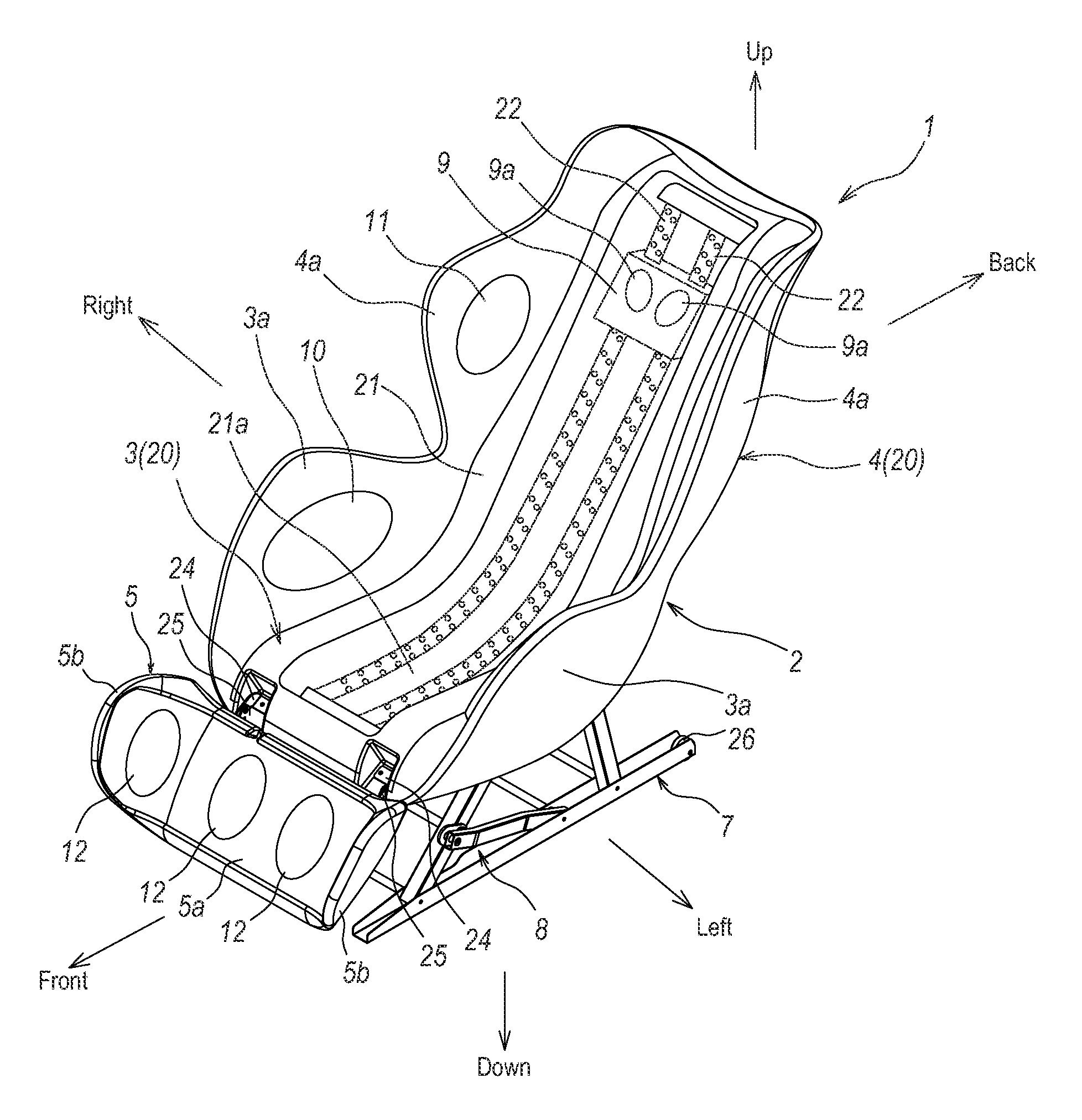
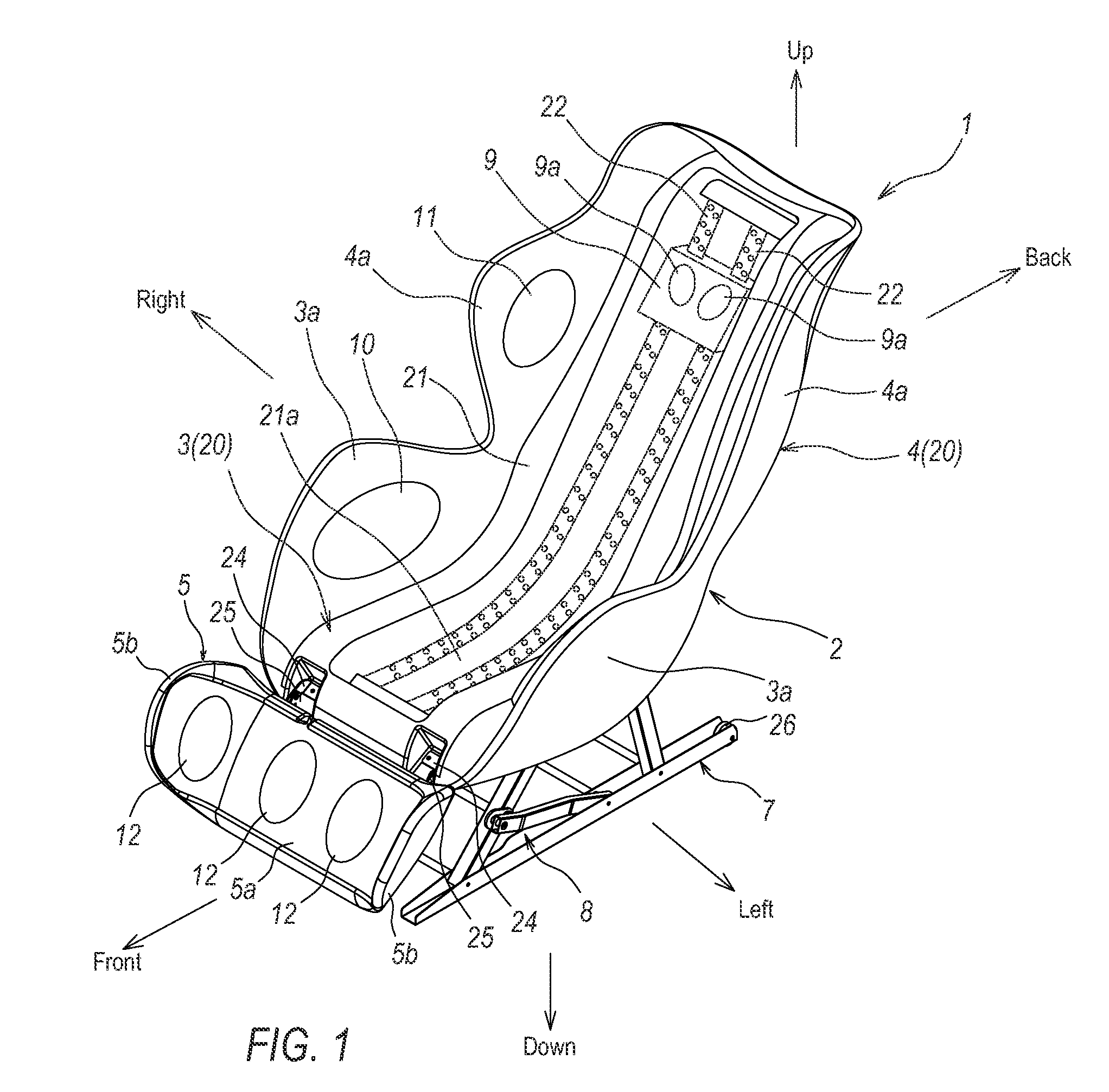
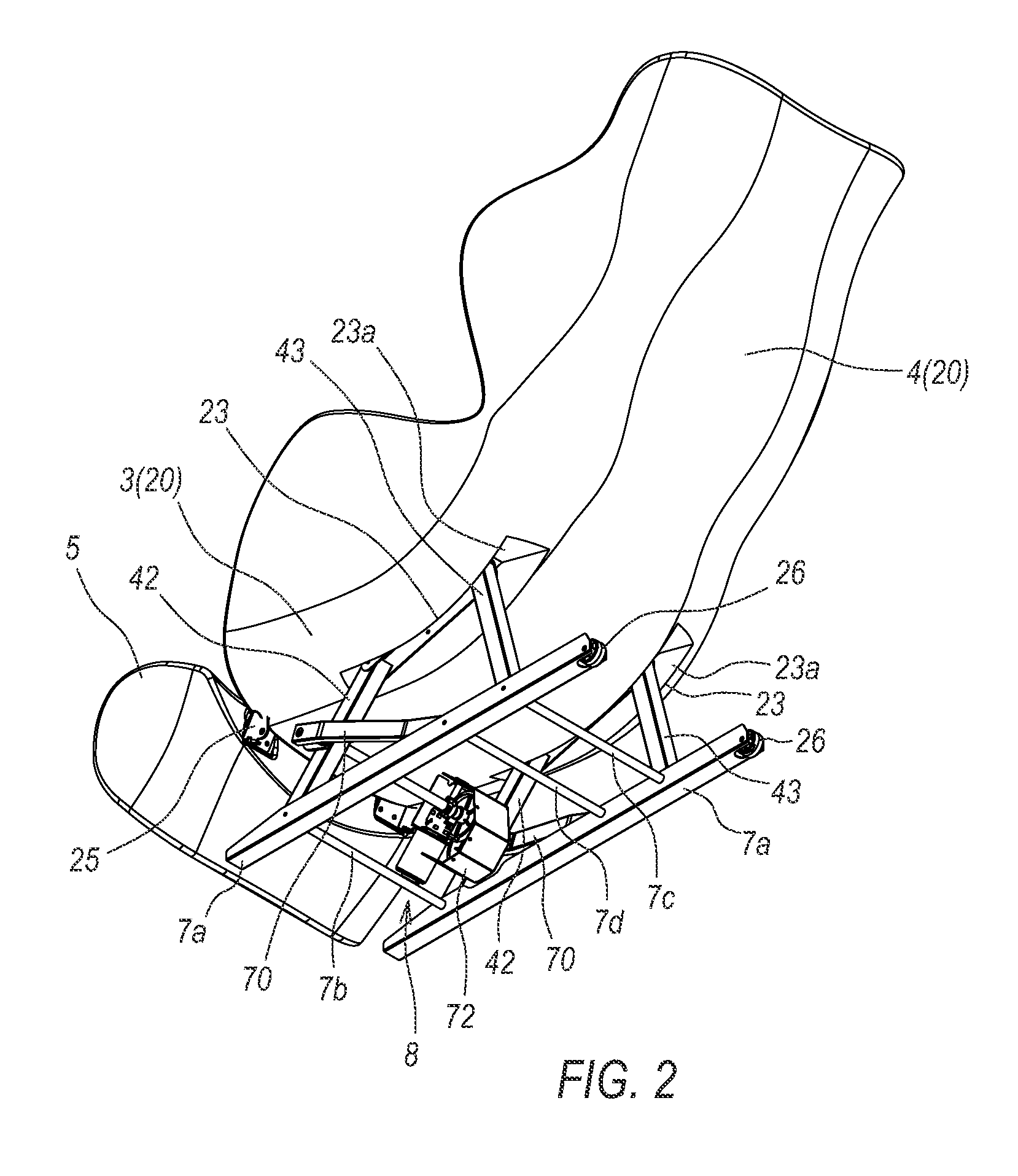
[0027]Hereinafter, description will be given of an overall configuration of a massage machine 1 according to a first embodiment of the present invention. FIG. 1 is a perspective view of the massage machine 1 according to the first embodiment of the present invention. FIG. 2 is a perspective view of the massage machine when viewed from a direction which is different from the direction in FIG. 1. FIG. 3 is a side view of the massage machine 1 in a standing state. FIG. 4 is a side view of the massage machine 1 in a reclining state. FIG. 5 is a perspective view showing a base 7 and a rocking mechanism portion 8. FIG. 6 is an explanatory diagram for illustrating the rocking mechanism portion 8. FIG. 7 is an explanatory diagram for illustrating operations of the rocking mechanism portion 8, where (a) shows the standing state, (b) shows an intermediate state, and (c) shows the reclining state. FIG. 8 is a functional block of the massage machine 1. In...

second embodiment

2. Second Embodiment

[0047]Hereinafter, description will be given of a massage machine 100 according to a second embodiment of the present invention with reference to the FIG. 9 and FIG. 10.

[0048]FIG. 9 is a side view showing a base 7 and a rocking mechanism portion 80 of the massage machine 100 according to the second embodiment of the present invention. FIG. 10 is a side view showing a motor 82 of a rocking drive unit 81. The same reference numerals are given to components that are the same as those in the massage machine 1 according to the aforementioned first embodiment, and the description thereof will be omitted. In addition, the configuration of the chair main body 2 is the same as that in the massage machine 1 according to the first embodiment. The massage machine 100 according to the second embodiment is different from that in the first embodiment in a configuration of the rocking mechanism portion 80. Specifically, the rocking mechanism portion 80 is configured mainly by li...


PUM


Abstract

A massage machine that can stably rock a chair main body in a forward-backward direction and that has minimal overall height comprising a chair main body, a base which supports the chair main body, massage portions provided in the chair main body, and a rocking mechanism portion which rocks the chair main body in the forward-backward direction with respect to the base. The rocking mechanism portion includes link members, each of which has a lower portion pivotally supported by the base and an upper portion pivotally supporting the chair main body. The chair main body is rocked in the forward-backward direction by rocking the upper portions of the link members in the forward-backward direction.

Description

CROSS REFERENCES TO RELATED APPLICATIONS[0001]This application claims priority from Japanese Patent Application Serial No. 2011-221460 filed Oct. 6, 2011, the contents of which are incorporated herein by reference in its entirety.BACKGROUND[0002]The present invention relates to a massage machine suitable for rocking a chair main body in a forward-backward direction.[0003]Conventionally, a massage machine has been known, in which a movable frame and a fixed frame are coupled to each other, a seat portion and a backrest portion are attached to the moveable frame, and a pivot point is set at a fulcrum Such a massage machine is capable of rocking the movable frame in the forward-backward direction about the pivot point with respect to the fixed frame by driving a rocking drive unit with a motor (see FIGS. 4 and 5 in Japanese Unexamined Patent Application Publication No. 2011-72595, for example).[0004]In addition, another massage machine has also been known, in which a supported portion ...

Claims


Application Information

Patent Timeline
IPC IPC(8): A47C3/02
CPCA61H2205/088A61H2201/1669A61H7/007A61H9/0078A61H2201/0149A61H2201/1215A61H2201/1436A61H2201/1463A61H2201/1633A61H2201/1676A61H2201/5002A61H2201/5007A61H2201/5064A61H2205/081A61H2205/10A47C3/02A61H1/003
Inventor NAGAMITSU, TOMOKI
Owner FAMILY INADA
Why Eureka
Try Eureka