
Robust metric computation of longitudinal position (LPOS) data symbol detection

a longitudinal position and data symbol technology, applied in the field of reading information, can solve the problems of low detection efficiency, low detection efficiency, and low detection efficiency, and achieve the effect of improving reducing the risk of noise and other disturbances, and ensuring the accuracy of lpos detection

Inactive Publication Date: 2013-04-11
IBM CORP
View PDF0 Cites 114 Cited by
  • Summary
  • Abstract
  • Description
  • Claims
  • Application Information

AI Technical Summary

Benefits of technology

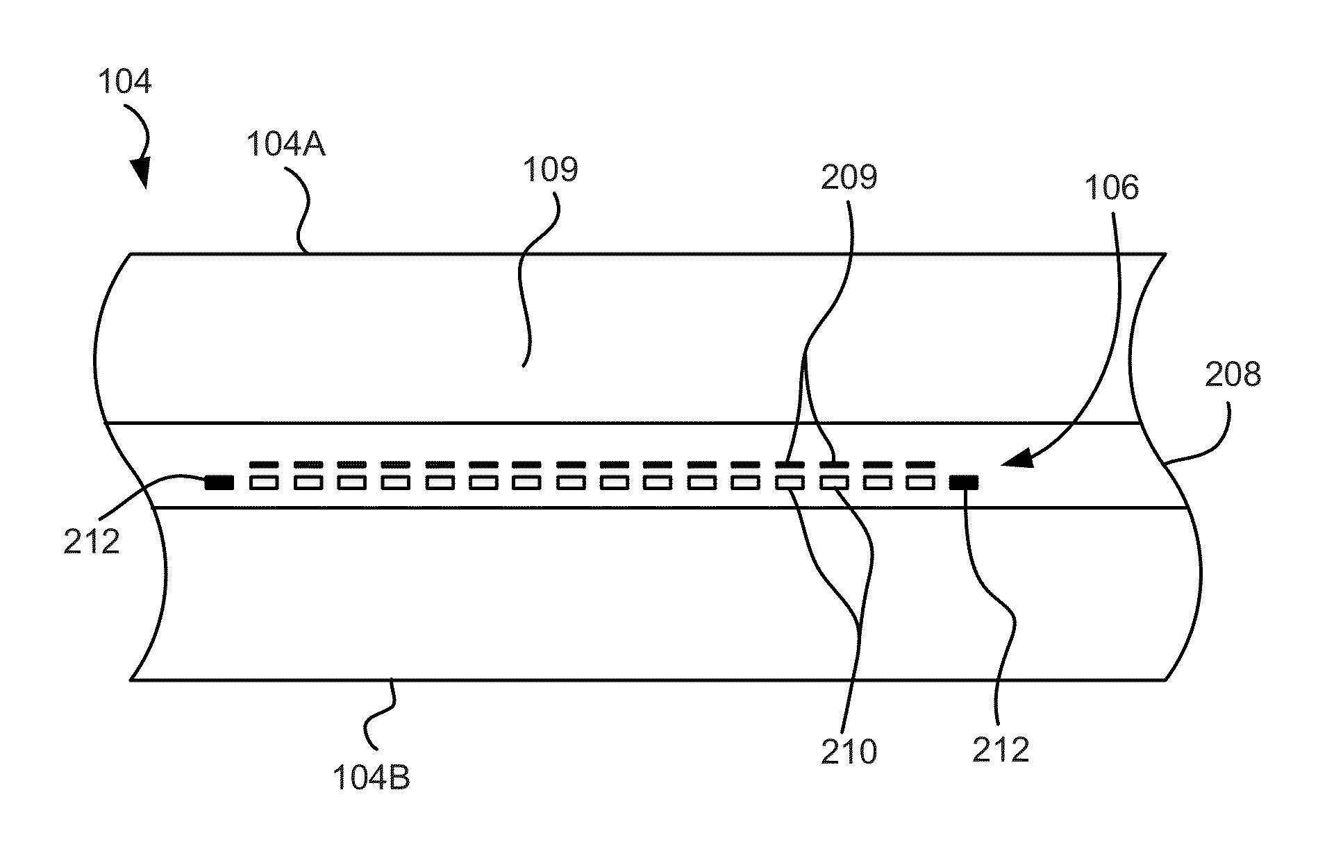
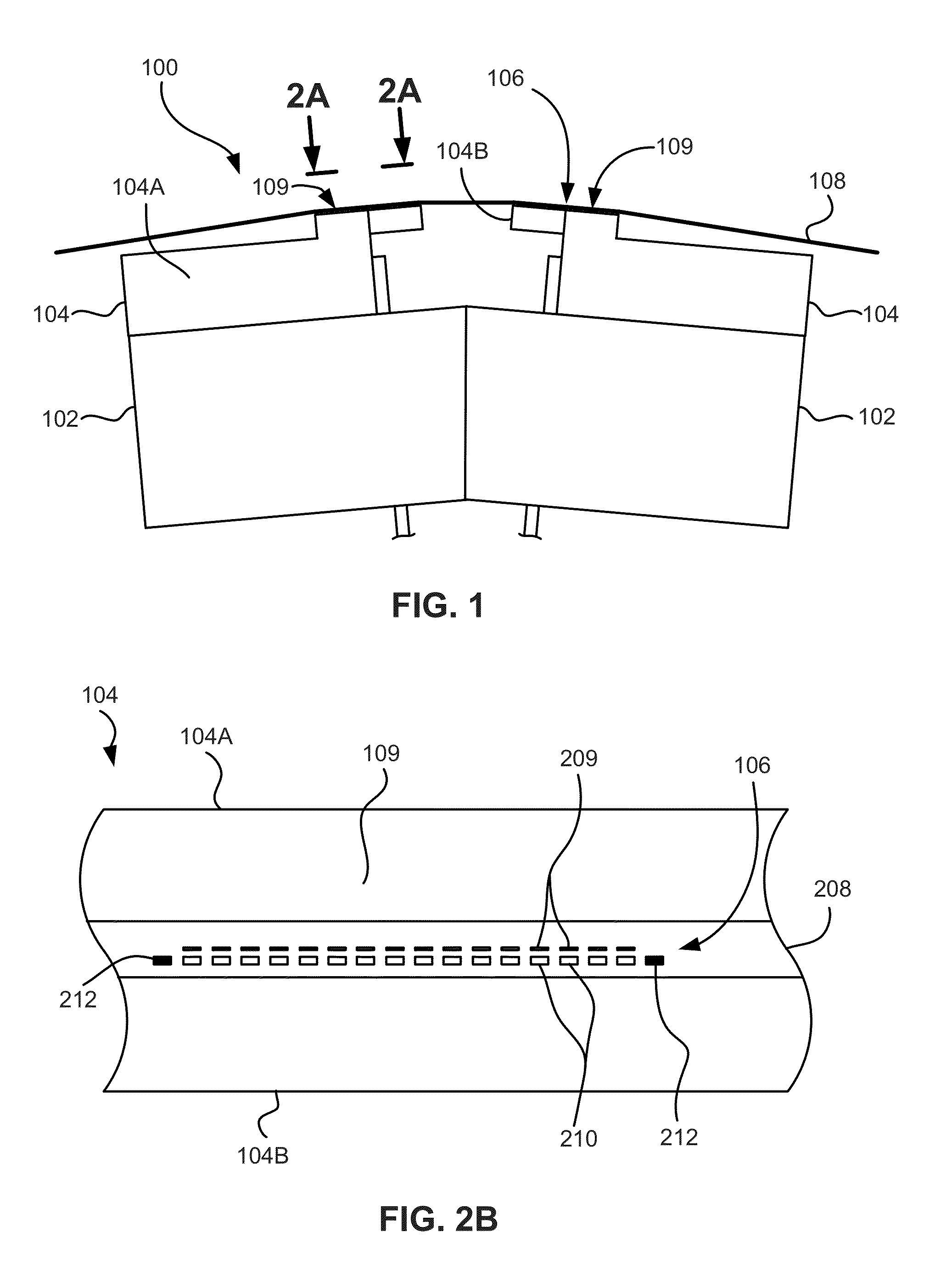
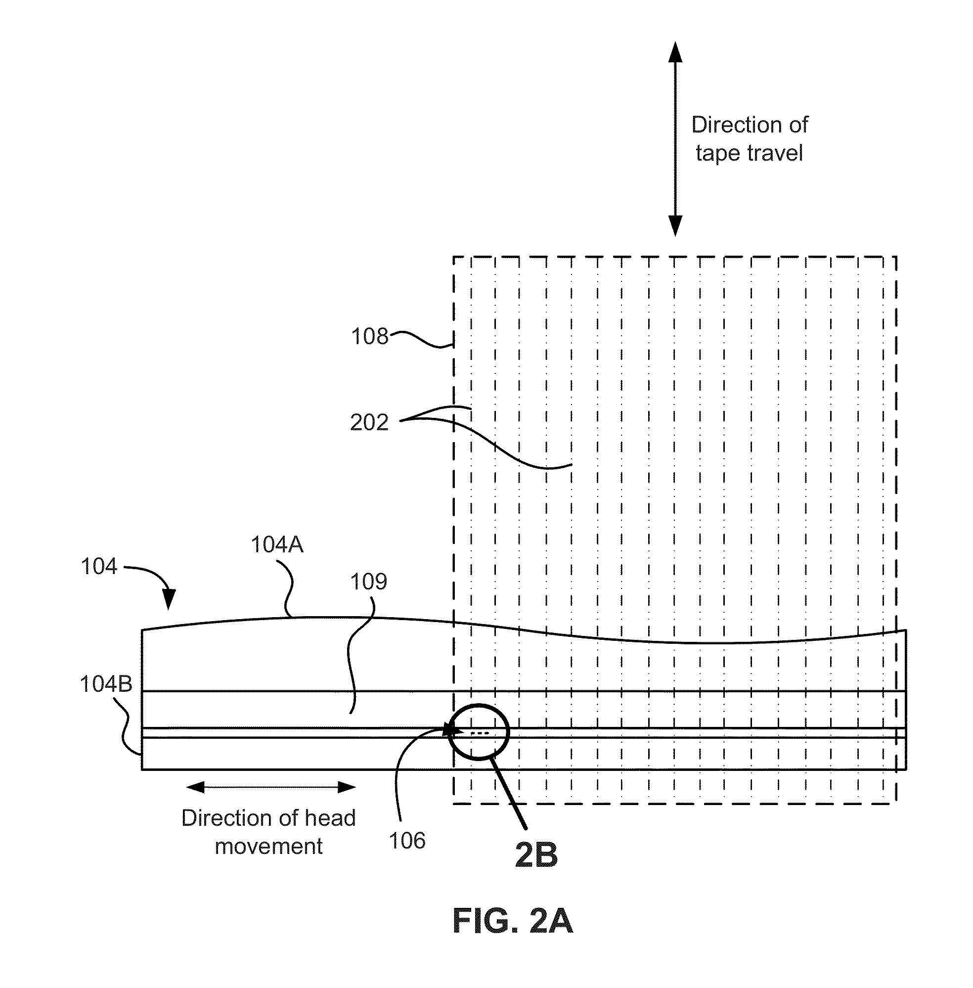
The patent describes a system and method for detecting and decoding data on a moving magnetic tape using servo pulses. The system includes a magnetic head that reads the servo pulses, an analog-to-digital converter that samples the readback servo signal, a digital correlator that computes a correlation signal between the sampled signal and a reference waveform, a timing reference module that provides interpolation instants to the correlator, an interpolator that interpolates the correlation signal at the instants to compute a longitudinal position detection metric, and a detector that decodes the encoded data symbol of the servo bursts and estimates its reliability. The system can accurately detect and decode the data on the servo tracks of the tape, even as it moves.

Problems solved by technology

If there is a mismatch between the two responses, as for example when tape cartridges exhibit significant deviation of the servo format parameters from the standard values, LPOS detection performance may be severely impaired and tape drive operation compromised.
Furthermore, currently implemented methods do not provide a high margin against noise and other disturbances at high tape velocity, as aliasing effects adversely affect the computation of the metric for LPOS detection based on matched filtering by a finite-impulse response digital filter using fixed filter coefficients from a down-sampled impulse response.

Method used


Image

  • Robust metric computation of longitudinal position (LPOS) data symbol detection
  • Robust metric computation of longitudinal position (LPOS) data symbol detection
  • Robust metric computation of longitudinal position (LPOS) data symbol detection

Examples


Embodiment Construction

[0029]The following description is made for the purpose of illustrating the general principles of the present invention and is not meant to limit the inventive concepts claimed herein. Further, particular features described herein can be used in combination with other described features in each of the various possible combinations and permutations.

[0030]Unless otherwise specifically defined herein, all terms are to be given their broadest possible interpretation including meanings implied from the specification as well as meanings understood by those skilled in the art and / or as defined in dictionaries, treatises, etc.

[0031]It must also be noted that, as used in the specification and the appended claims, the singular forms “a,”“an,” and “the” include plural referents unless otherwise specified.

[0032]The following description describes gathering information from a servo track when operating a tape drive, and more particularly to using a robust metric computation for longitudinal posi...


PUM

PropertyMeasurementUnit
velocityaaaaaaaaaa
velocityaaaaaaaaaa
velocityaaaaaaaaaa

Abstract

In one embodiment, a tape drive system includes a magnetic head having a servo sensor for sensing a defined servo track of a magnetic tape and configured to read servo pulses from servo bursts of the servo track while the magnetic tape is moving past the magnetic head with the servo bursts representing an encoded data symbol, an analog-to-digital converter configured to provide a sequence of samples of the readback servo signal, a digital correlator configured to compute a correlation signal between the sequence and a reference waveform, a timing reference module configured to provide a reference timing model having interpolation instants to the digital correlator, a correlation interpolator configured to interpolate the correlation signal at the interpolation instants and compute a longitudinal position (LPOS) detection metric, and an LPOS detector configured to decode the encoded data symbol of the servo bursts using the computed LPOS detection metric.

Description

BACKGROUND[0001]The present invention relates to reading information from a servo track in a longitudinal tape system, and more particularly, to using a robust metric computation for longitudinal position (LPOS) symbol detection.[0002]Timing-based servo (TBS) systems utilize technology that was developed specifically for linear tape drives. In TBS systems, recorded servo patterns have transitions with two different azimuthal slopes. The head lateral position is derived from the relative timing of pulses generated by a servo reader reading the pattern. The servo patterns are written on five dedicated servo bands that straddle four data bands. A specification for the servo patterns in current tape drives is provided by the linear tape-open (LTO) format. The complete format for LTO drives of generation 1 (LTO-1) was standardized by the European Computer Manufacturers Association (ECMA) in 2001 as ECMA-319. Additional information on LTO technology, in particular on LTO drives of generat...

Claims


Application Information

Patent Timeline
Patent Type & Authority Applications(United States)
IPC IPC(8): G11B5/58
CPCG11B5/584G11B20/1201G11B20/1202G11B2020/1281G11B2220/956G11B2220/93G11B20/10231G11B20/10287G11B2220/90G11B20/10037
Inventor CHERUBINI, GIOVANNIJELITTO, JENSHUTCHINS, ROBERT A.
Owner IBM CORP
Learn More