
Smart power supply system for minimizing power consumption during device standby

Inactive Publication Date: 2013-04-18
MOK HANLIN +1
View PDF3 Cites 38 Cited by
  • Summary
  • Abstract
  • Description
  • Claims
  • Application Information

AI Technical Summary

Benefits of technology

The invention is based on a smart power supply system that aims to minimize standby power consumption by optimizing the charging cycle of a power storage device. It uses a learning controller to detect the minimum energy level of the device and learning from external information, such as electricity rates, to determine the optimal time to recharge the device. The system also includes a mains to device power converter for appliance manufacturers who want to reduce standby power consumption. The smart power supply system can be used as a control point between mains power and a legacy electronic device or it can be used to control and switch mains power of existing equipment or appliance to reduce their standby power consumption.

Problems solved by technology

However, even this smaller amount of electricity consumption can be significant when multiplied by millions or billions of units.

Method used


Image

  • Smart power supply system for minimizing power consumption during device standby
  • Smart power supply system for minimizing power consumption during device standby
  • Smart power supply system for minimizing power consumption during device standby

Examples


Embodiment Construction

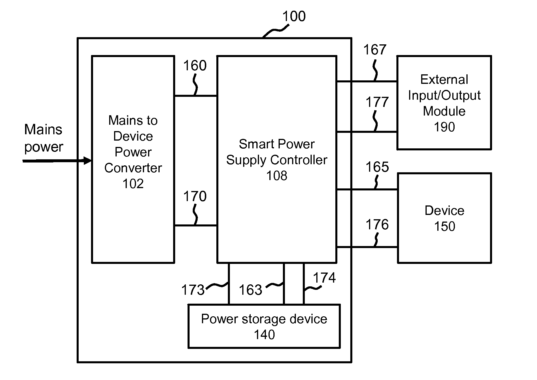
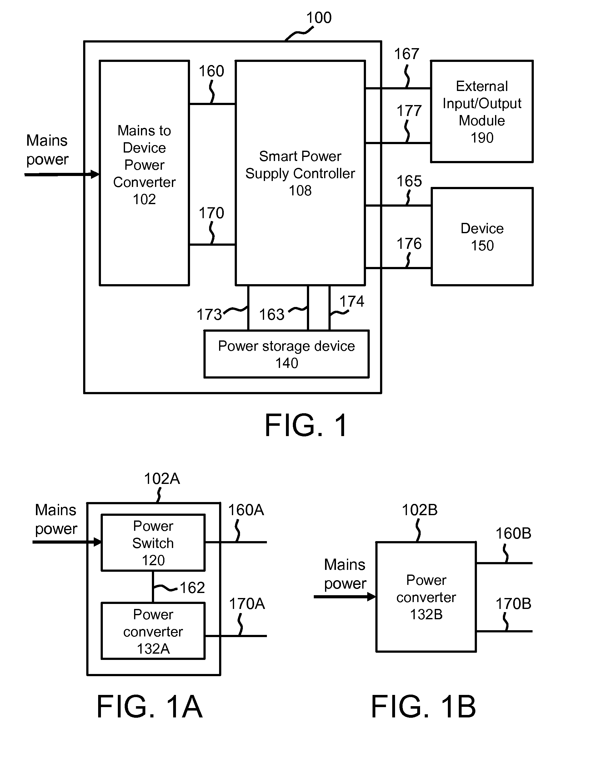
[0033]One embodiment of the smart power supply system 100 is illustrated in FIG. 1. The present invention will now be described with reference to the drawings wherein like reference numerals are used to refer to like elements throughout. It will be appreciated that the drawings may not be to scale.

[0034]The smart power supply system 100 of the present invention is powered by the mains power that is used to regulate power to an electronic device 150 connected by means of electrical connectors (not shown). Such electronic devices may be the electrical circuits in a computer, television or an electrical appliance. As will be explained in more details below, the smart power supply system 100 includes a mains to device power converter 102, a smart power supply controller 108 and a power storage device 140 that is normally connected to a device 150, and an external controller input and output module 190. The smart power supply controller 108 sends a control signal via line 160 to switch o...


PUM


Abstract

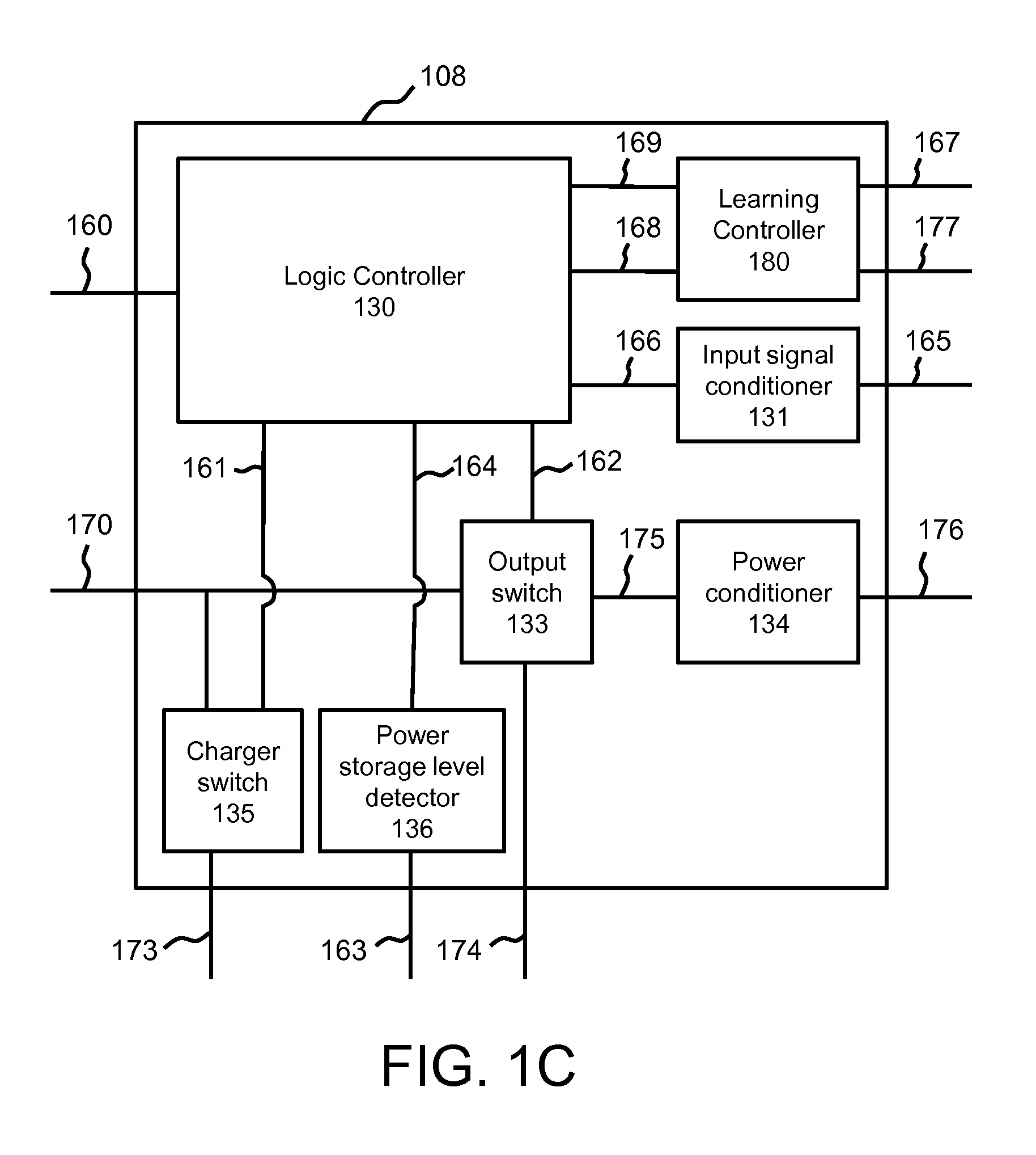
The present invention discloses a smart power supply system for electrical appliances, using a rechargeable power storage device, a logic controller, and a learning controller, to control and minimize electricity consumption from mains power during standby. In standby mode, when only a small amount of electrical power is needed, energy from the power storage device is used and mains power is disconnected unless the power storage device requires a recharge. A logic controller senses the appliance's operating state, using it to determine when power should be supplied from mains power or the power storage device. A learning controller monitors and stores historical characteristics of the power storage device's charge and discharge cycles, using them to automatically calculate new recharge cycle parameters to minimize mains power consumption. An external input and output module enable users, computers and electronic devices to interact and program the learning controller.

Description

CROSS-REFERENCE TO RELATED APPLICATIONS [0001]Not ApplicableFEDERALLY SPONSORED RESEARCH [0002]Not ApplicableSEQUENCE LISTING OR PROGRAM [0003]Not ApplicableFIELD OF THE INVENTION[0004]This application relates generally to the field of electrical household appliances, particularly to an electronic control device for a power supply that can minimize power consumption of appliance by utilizing energy from a power storage device during standby.BACKGROUND OF THE INVENTION[0005]Electrical appliances and devices such as televisions, battery chargers, home computers and computer printers, seldom operate in their fully functional mode, or ‘on’ mode, all the time. Instead, they are mostly on ‘standby’ mode or ‘sleep’ mode, whereby power consumption is significantly lowered. In addition to saving power and reducing wear and tear of an appliance, standby mode can also reduce startup time as well as enabling startup via remote control. During standby, an appliance uses a relatively small amount...

Claims


Application Information

Patent Timeline
IPC IPC(8): H02J9/00H02B1/00
CPCH02J9/005Y04S20/20Y02B70/30
Inventor MOK, HANLINMOK, SWEE MEAN
Owner MOK HANLIN
Learn More