A color tunable lamp including a control device with a relative flux sensor

a control device and sensor technology, applied in the field of flux sensors, can solve the problems of limiting the design of light sources comprising a plurality of light emitters, the method and system the cost of the calibrated light intensity sensor of the cited patent application, so as to achieve the effect of less cos

Inactive Publication Date: 2013-04-18
KONINKLIJKE PHILIPS ELECTRONICS NV
View PDF2 Cites 9 Cited by
  • Summary
  • Abstract
  • Description
  • Claims
  • Application Information

AI Technical Summary

Benefits of technology

[0009]It is an object of the invention to provide a method and a system for character

Problems solved by technology

For example, the light emitter may deviate from the manufacturing specifications, or deviate from the light emitters of the sample of which the characteristics were measured, or deviate over time because of drift and degradation.
The calibrated light intensity sensor of the cited patent application is a relatively expensive part of the system.
Furthermore, to measure the maximum light inten

Method used


Image

  • A color tunable lamp including a control device with a relative flux sensor
  • A color tunable lamp including a control device with a relative flux sensor
  • A color tunable lamp including a control device with a relative flux sensor

Examples


first embodiment

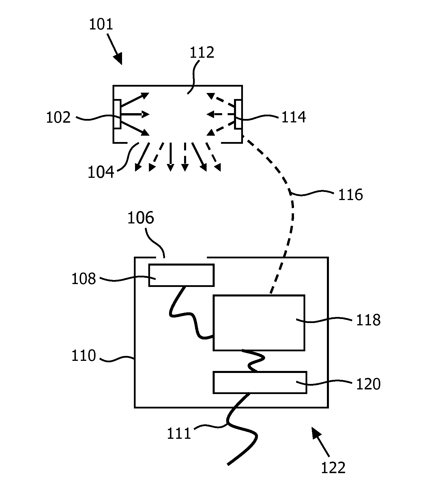
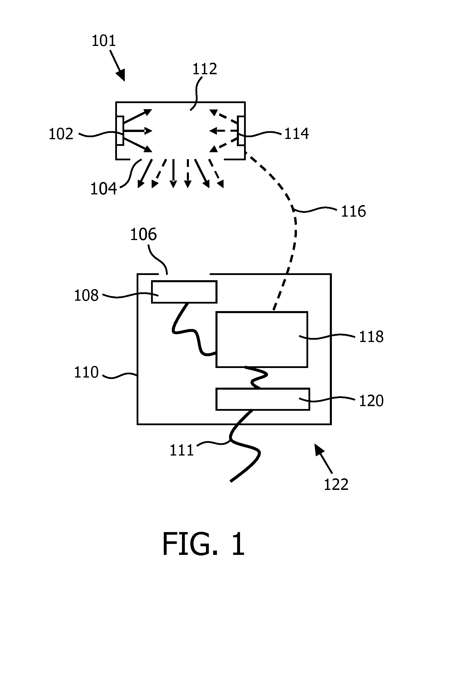
[0067]A first embodiment is shown in FIG. 1. A light source 101 is shown which comprises a first Light Emitting Diode (LED) 102 and a second LED 114. The first LED 102 emits light of a first color into a light mixing chamber 112 of the light source 101. The second LED 114 emits light of a second color into the light mixing chamber 112. The second color is different from the first color. The light mixing chamber 112 comprises a light exit window 104. Light which is a mixture of the first color and the second color is emitted through the light exit window 104 into the ambient of the light source 101.

[0068]A relative flux sensor 122 is shown as well. The relative flux sensor 122 comprises a light input 106 through which light may enter the relative flux sensor 122 to impinge on a color point sensor 108. The color point sensor 108 is coupled to a sensor controller 118 of the relative flux sensor 122. The sensor controller 118 is coupled to the output means 120.

[0069]The color point sens...

second embodiment

[0100]Alternatively, in a second embodiment, the dimming factors D1, D5 and D9 are 100% and the dimming factors D2, D3, D4, D6, D7, and D8 are 0%. The sensor controller 418 is further arranged to provide a fifth signal to the light source 402. The fifth signal comprises the dimming factors D1, D5 and D9. When the light source 402 emits according to the fifth signal, the sensor controller 418 receives the measuring signal from the color point sensor 108 representing a fifth color point. The sensor controller 418 is arranged to calculate the first ratio between the maximum flux of the first OLED 401 and the maximum flux of the second OLED 403 on the basis of the dimming factors D1 to D9 and the first color point, the second color point, the fourth color point and the fifth color point. Additionally, the sensor controller may be arranged to calculate the second ratio between the maximum flux of the first OLED 401 and the maximum flux of the third OLED 412 on the basis of the dimming fa...


PUM


Abstract

A relative flux sensor (122) and a method of characterizing characteristics of light emitters are provided. The relative flux sensor (122) comprises a color point sensor (108) and a sensor color (118). The color point sensor (108) measures a color point in a color space of light emitted by a light source (101) comprising a first light emitter (102) for emitting light of a first color and a second light emitter (114) for emitting light of a second color being different from the first color. The light source (101) is arranged for emitting light of a controllable color, being a mix of light of the first color and light of the second color. The sensor controller (118) is coupled to the color point sensor (108) for receiving a measuring signal and is arranged for i) providing a first signal to the light source (101), the first signal comprising a dimming factor D1 and a dimming factor D2, the dimming factor D1 and the dimming factor D2 indicating a fraction of a maximum flux of the first light emitter (102) and the second light emitter (114), respectively, and receiving the measuring signal representing a first color point when the light source (101) emits light according to the first signal, wherein at least one of the dimming factors D1 and D2 is different from 0, ii) providing a second signal to the light source (101), the second signal comprising a dimming factor D4 and a dimming factor D5, the dimming factor D4 and the dimming factor D indicating a fraction of the maximum flux of the first light emitter (102) and the second light emitter (114), respectively, and receiving the measuring signal representing a second color point when the light source (101) emits light according to the second signal, wherein both dimming factors D4 and D5 are different from 0, iii) calculating within a model of the color 20 space a ratio between a maximum flux of the first light emitter (102) and a maximum flux of the second light emitter (114) on the basis of the first color point, the second color point, the dimming factors D1, D2, D4 and D5.

Description

FIELD OF THE INVENTION[0001]The invention relates to the field of flux sensors.BACKGROUND OF THE INVENTION[0002]In a color-tunable lamp, colors are created by mixing the light of at least two light emitters which each emit light of a different color. A first light emitter emits, for example, light of a first color which may be defined by a first color point (x1, y1) in a color space. A second light emitter emits, for example, light of a second color which may be defined by a second color point (x2, y2) in the color space. The emission of a specific amount of light of the first color relative to the emission of a specific amount of light of the second color, causes a specific mixed color defined by the third color point (x12, y12) to be emitted, which is located in between the first color point and the second color point on a line through the first color point and the second color point. By accurately controlling the ratio between the amount of light emitted by the first light emitte...

Claims


Application Information

Patent Timeline
IPC IPC(8): H05B37/02H05B44/00
CPCH05B37/02H05B33/0869H05B45/22H05B47/10
Inventor VINKENVLEUGEL, LUCIUS THEODORUSMCCORMACK, JAMES JOSEPH ANTHONYMEEUSEN, JORGEN
Owner KONINKLIJKE PHILIPS ELECTRONICS NV
Why Eureka
Try Eureka