Capacitive Differential Quadrature Rotary Position Sensor

a rotary position sensor and differential quadrature technology, applied in the field of rotation sensors, can solve the problems of lack of resolution of rotary sensors known in the art, and achieve the effect of minimum capacitive coupling and maximum capacitive coupling

Inactive Publication Date: 2013-04-18
THE BOARD OF TRUSTEES OF THE LELAND STANFORD JUNIOR UNIV
View PDF1 Cites 23 Cited by
  • Summary
  • Abstract
  • Description
  • Claims
  • Application Information

AI Technical Summary

Benefits of technology

[0008]In another aspect of the invention, the conductive pads have a ground connection and an active shield connection, where the ground connection provides a relatively maximum capacitive coupling to the sensing disc, and the active shield coupling provides a relatively minimum ca

Problems solved by technology

Rotary sensors known in the art are lacking in resolution and generally have an oversized form factor, making them impractical for applications requiring maximum signal production f

Method used


Image

  • Capacitive Differential Quadrature Rotary Position Sensor
  • Capacitive Differential Quadrature Rotary Position Sensor
  • Capacitive Differential Quadrature Rotary Position Sensor

Examples


Embodiment Construction

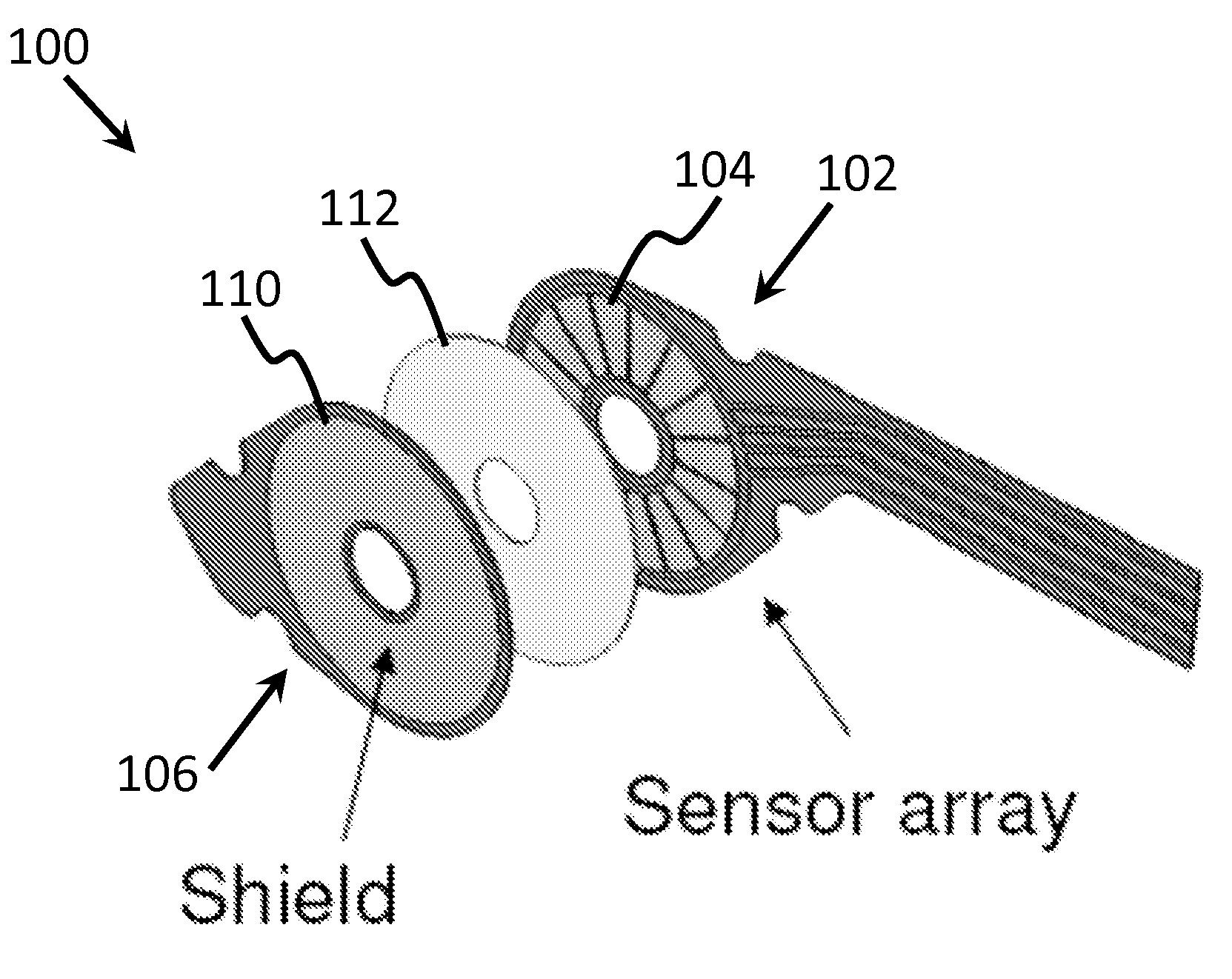
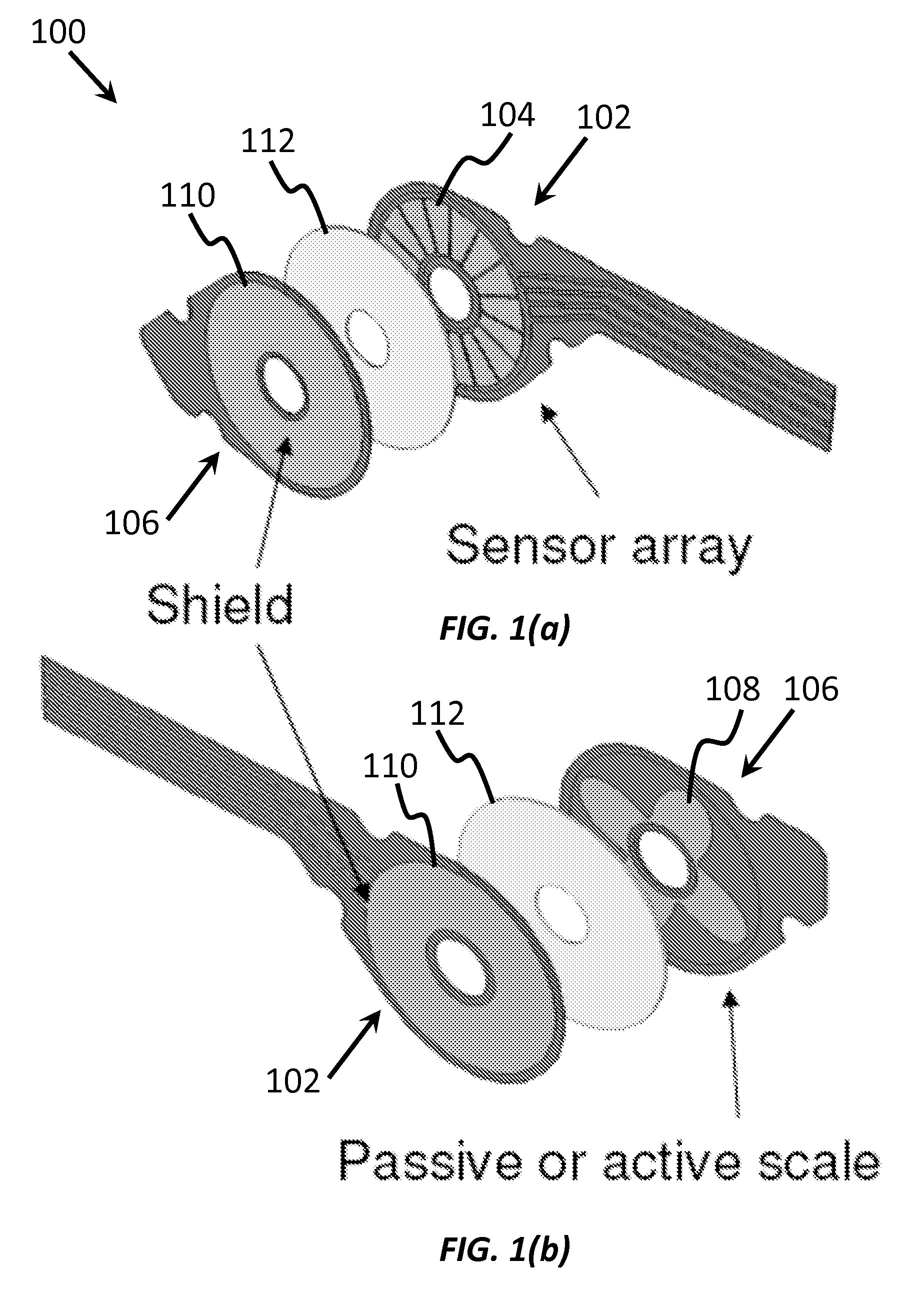
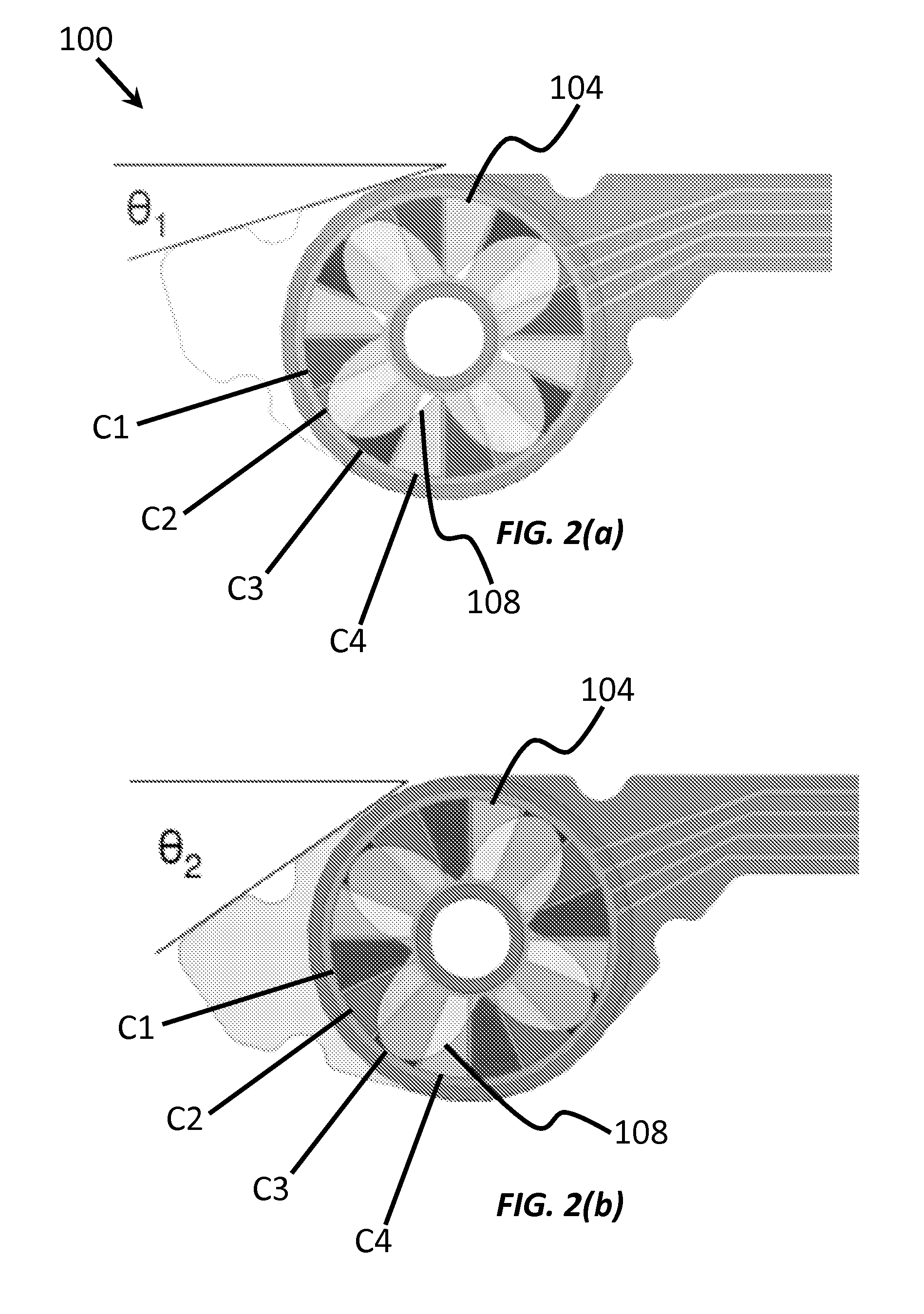
[0014]The present work provides an improved capacitive angular position sensor. FIGS. 1a-1b and FIGS. 2a-2b show different views of capacitive angular position sensor 100, according to one embodiment of the invention. Here, two flat discs are patterned with conductive material and laid over one another creating capacitive coupling between the two discs at the conductor locations. One disc, referred to as the sensing disc 102, has 4 capacitive sensing pads 104 labeled C1, C2, C3 and C4, that appear in at least 8 locations (at least 2 locations each) in a regular pattern around the surface of the sensing disc 102. In general, each capacitive sensing pad 104 has N-fold rotational symmetry (N≧2), and the overall pattern formed by all capacitive sensing pads 104 has 4N-fold rotational symmetry. The other disc, which will be referred to as the scale 106, has a pattern of rounded conductive pads 108 on its surface that produces four sinusoidal waveforms in capacitance, each 90 degrees out ...


PUM


Abstract

A rotary position sensor is provided that includes a sensing disc having an N-fold rotation symmetry and capacitive sensing pads arranged in an array pattern, where the array pattern has at least 4N-fold rotation symmetry, where N≧2, a scale disc disposed opposite the sensing disc, where the scale disc includes a pattern of conductive pads that have a sinusoidal-shape, where the pattern of sinusoidal-shaped conductive pads produce four sinusoidal capacitance waveforms in quadrature phase with the capacitive sensing pads as the sensing disc and the scale disc are rotated relative to one another to provide angular position information. to provide angular position information. This is achieved by making the overlapping area of the of the capacitive sensing pads change in a sinusoidal fashion with rotation.

Description

CROSS-REFERENCE TO RELATED APPLICATIONS[0001]This application claims priority from U.S. Provisional Patent Application 61 / 627786 filed Oct. 18, 2011, which is incorporated herein by reference.STATEMENT OF GOVERNMENT SPONSORED SUPPORT[0002]This invention was made with Government support under contract W91CRB-10-C-0139 awarded by Defense Advanced Research Projects Agency. The Government has certain rights in this invention.FIELD OF THE INVENTION[0003]The current invention relates to rotation sensors. More particularly, the invention relates to a capacitive angular position sensor.BACKGROUND OF THE INVENTION[0004]It is often desirable to sense the angular position of a rotating part. Numerous kinds of rotation sensors have been developed over the years. One type of rotation sensor is a capacitive sensor, where a capacitance varies according to angular position. Rotary sensors known in the art are lacking in resolution and generally have an oversized form factor, making them impractical...

Claims


Application Information

Patent Timeline
IPC IPC(8): G01B7/30
CPCG01D5/2415
Inventor ULMEN, JOHN V.HEYNEMAN, BARRETT E.
Owner THE BOARD OF TRUSTEES OF THE LELAND STANFORD JUNIOR UNIV
Why Eureka
Try Eureka