

Information processing device
- Summary
- Abstract
- Description
- Claims
- Application Information
AI Technical Summary
Benefits of technology
Problems solved by technology
Method used
Image

Examples
first interface example
[0096]When the mobile information terminal in this embodiment has been placed in an operation mode in which, for example, characters are entered, if areas on each of which a touch was detected on the rear touch panel 27 are of at least a predetermined size and the number of these touch detecting areas of at least the predetermined size is, for example, two or more, the terminal displays a keyboard in a predetermined form (so-called QWERTY keyboard in this example) on the screen of the display panel 21 as a first interface in this embodiment. The predetermined size and the number of touch detecting areas of at least the predetermined size will be described below in detail.
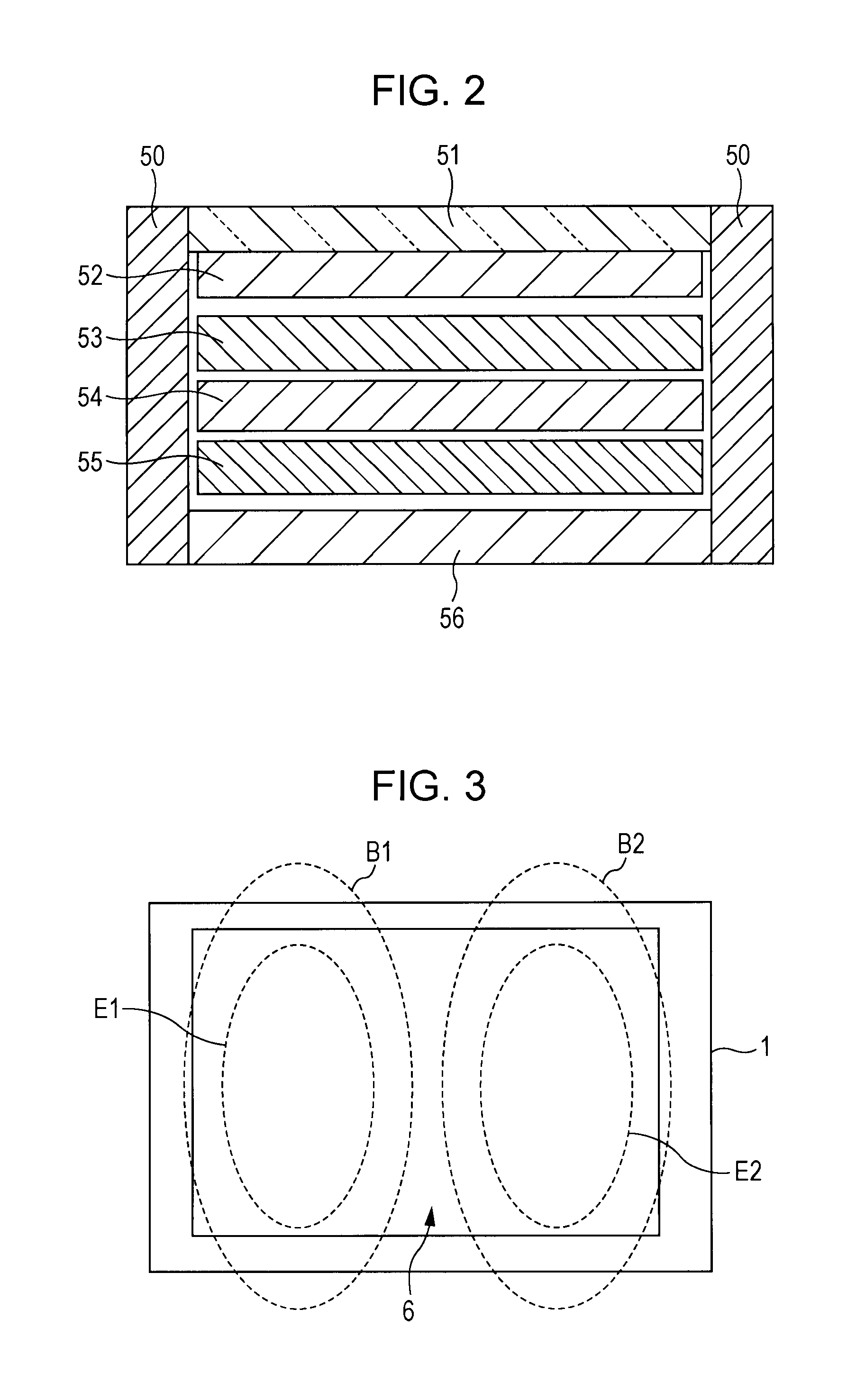
[0097]If two touch detecting areas E1 and E2 of at least the predetermined size are detected on the panel surface 6 of the rear touch panel 27 as shown in, for example, FIG. 3, the mobile information terminal 1 in this embodiment displays a QWERTY keyboard 3Q including keys, each of which has a size suitable for use...
second interface example
[0102]When the mobile information terminal in this embodiment has been placed in an operation mode in which, for example, characters are entered, if all areas on each of which a touch was detected on the rear touch panel 27 are smaller than the predetermined size and the number of touch detecting areas smaller than the predetermined size is, for example, five or more, the terminal divides a QWERTY keyboard into two parts. Then, the mobile information terminal displays one of them in the vicinity of the right edge of the screen of the display panel 21 and also displays the other in the vicinity of the left edge of the screen of the display panel 21 as a second interface of this embodiment. The predetermined size and the number of touch detecting areas smaller than the predetermined size will be described below in detail.
[0103]If, for example, all that were detected on the panel surface 6 of the rear touch panel 27 are five or more touch detecting areas smaller than the predetermined ...
third interface example
[0115]When the mobile information terminal in this embodiment has been placed in an operation mode in which, for example, characters are entered, if all areas on each of which a touch was detected on the rear touch panel 27 are smaller than the predetermined size and the number of touch detecting areas smaller than the predetermined size is, for example, four or less, the terminal places and displays a keyboard in a predetermined form (a so-called keyboard having 10 keys) at a location, on the screen of the display panel 21, that corresponds to the positions at which touches were detected on the rear touch panel 27, as a third interface in this embodiment. The predetermined size and the number of touch detecting areas smaller than the predetermined size will be described below in detail.
[0116]If, for example, as shown in FIG. 12, all that were detected on the panel surface 6 of the rear touch panel 27 are at most four touch detecting areas smaller than the predetermined size (four t...
PUM
 Abstract
Description
Claims
Application Information