Illumination device

a technology of illumination device and spherical tube, which is applied in the direction of coatings, point-like light sources, lighting and heating apparatus, etc., can solve the problems of unpleasant brightness called “glare”, cannot be used for indoor illumination device, and cannot be modified, so as to achieve low light transmissivity, high efficiency, and high light reflectivity

Inactive Publication Date: 2013-04-18
OPTO DESIGN INC
View PDF6 Cites 11 Cited by
  • Summary
  • Abstract
  • Description
  • Claims
  • Application Information

AI Technical Summary

Benefits of technology

[0008]The ultrafinely foamed reflection plate that is used in the illumination device disclosed in Patent Document 3 has the advantage of being lightweight and easily processable, for example, easily drillable, but is difficult to thermally weld when the casing is assembled. This is because the ultrafinely foamed reflection plate is formed from plastic with thermoplasticity, and when heated, the gases contained in it are released, with the result that it shrinks or its light reflectivity lowers, and its properties change. Polyethylene terephthalate resin (hereinafter referred as to “PET”) is used in the ultrafinely foamed reflection plate, and PET is generally a poor-adhesivity substance, making adhesion using an adhesive difficult.

Problems solved by technology

The planar light sources that are used for indoor illumination devices and the like are required to emit light uniformly, but since LEDs have strong light directionality, they are not suitable, without modification, to be used for indoor illumination devices.
The strong-directionality light of LEDs causes unpleasant brightness called “glare” when it enters eyes directly.

Method used


Image

  • Illumination device
  • Illumination device
  • Illumination device

Examples


embodiment 1

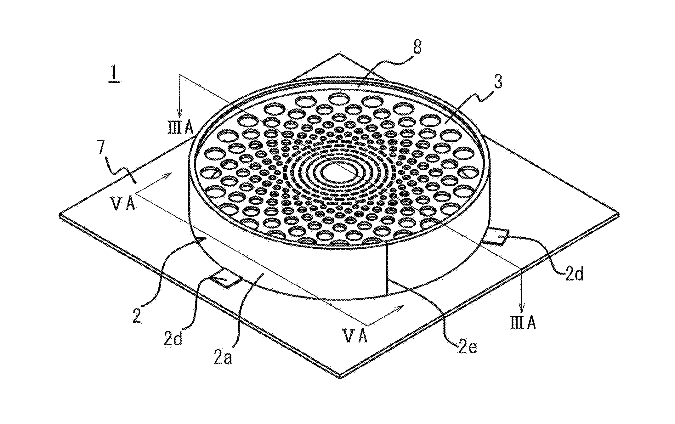
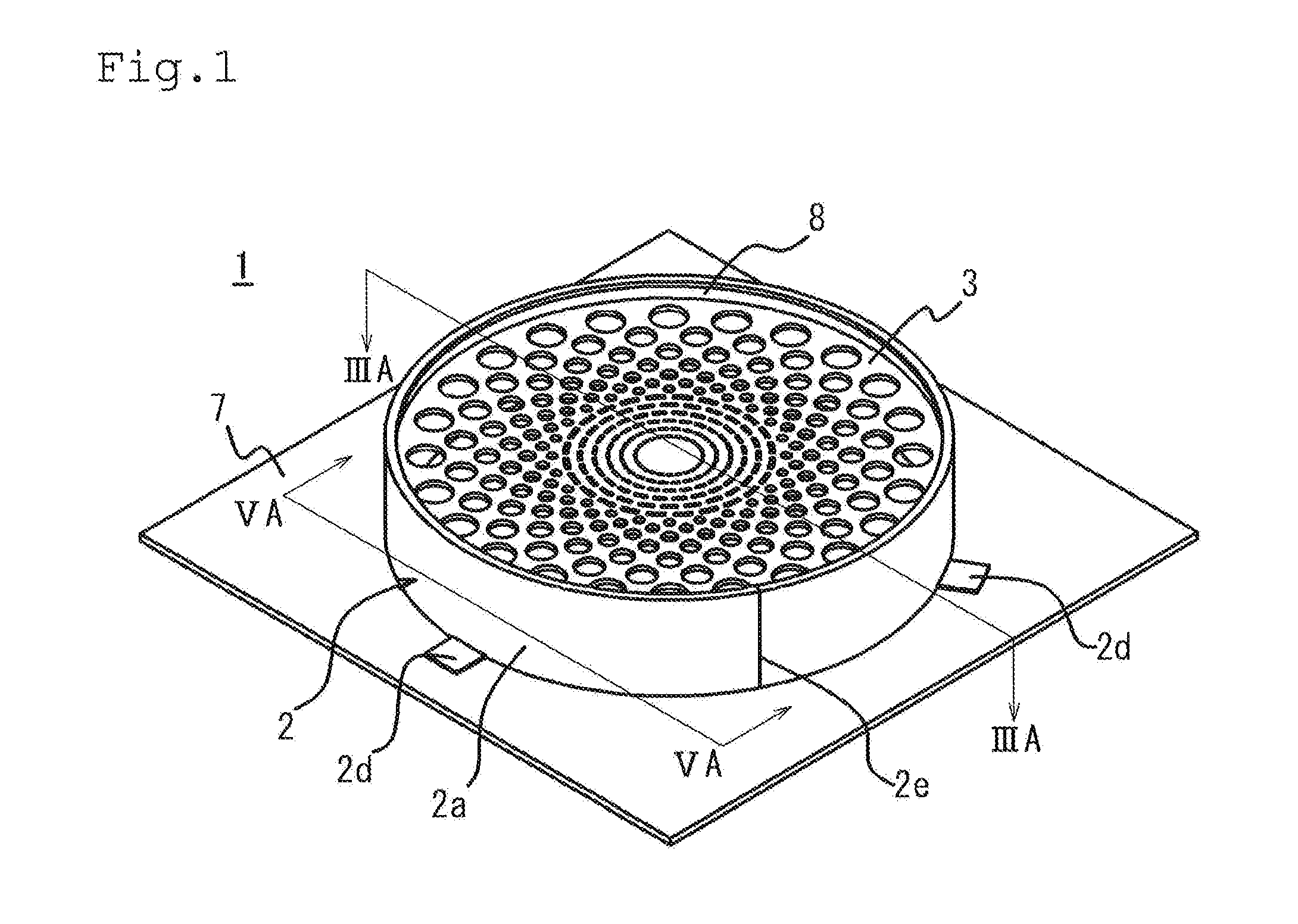
[0052]First of all, the illumination device of Embodiment 1 of the invention will be described with reference to FIGS. 1 to 5. FIG. 1 is a perspective view of the illumination device in Embodiment 1 of the invention. FIG. 2 is an exploded perspective view of the illumination device in FIG. 1. FIG. 3A is a sectional view along line IIIA-IIIA in FIG. 1, FIG. 3B is an enlarged view of portion IIIB in FIG. 3A, and FIG. 3C is an enlarged view of portion IIIC in FIG. 3A. FIG. 4 is a top view of the light conducting reflection plate in Embodiment 1 of the invention. FIG. 5A is a sectional view along line VA-VA in FIG. 1, and FIG. 5B is an enlarged view of portion VB in FIG. 5A.

[0053]The illumination device 1 of this embodiment is assembled by providing a protective plate 8, a light conducting reflection plate 3, and a side surface reflection section 4 inside a frame 2, and installing the frame 2 to a substrate 7 to which a bottom surface reflection section 5 and a point light source 6 are ...

embodiment 2

[0071]Next, an illumination device of Embodiment 2 of the invention will be described with reference to FIGS. 7 to 9. FIG. 7A is a sectional view of the illumination device in Embodiment 2 of the invention, and FIG. 7B is an enlarged view of portion VIIB in FIG. 7A. FIG. 8 is a schematic illustrating an example of fire retardance processing on the light conducting reflection plate in FIG. 7. FIG. 9 is a schematic illustrating another example of fire retardance processing on the light conducting reflection plate in FIG. 7.

[0072]The illumination device of Embodiment 2 has the structure of the illumination device of Embodiment 1 with partial alterations. Note that in the following description, those structural components that are shared with the illumination device of Embodiment 1 are assigned the same reference numerals and descriptions thereof are omitted as redundant, while the structural components that differ will be described in detail.

[0073]The illumination device of Embodiment ...

embodiment 3

[0075]Next, an illumination device of Embodiment 3 of the invention will be described with reference to FIGS. 10 and 11. FIG. 10A is a top view of a diffuser plate used in the illumination device of Embodiment 3 of the invention, FIG. 10B is a sectional view along line XB-XB in FIG. 10A, FIG. 10C is another example of a top view of a diffuser plate used in the illumination device of Embodiment 3 of the invention, and FIG. 10D is a cross-sectional view along line XD-XD in FIG. 10C. FIG. 11 is a perspective view of the illumination device of Embodiment 3 of the invention.

[0076]The illumination device of Embodiment 3 has the structure of the illumination device of Embodiment 1 with partial alterations. Note that in the following description, those structural components that are shared with the illumination device of Embodiment 1 are assigned the same reference numerals and descriptions thereof are omitted as redundant, while the structural components that differ will be described in de...


PUM

PropertyMeasurementUnit
light reflectivityaaaaaaaaaa
diameteraaaaaaaaaa

Abstract

An illumination device includes: a point light source; a substrate; a hollow frame having an engaging bent section at one of its edges; and a bottom surface reflection section, a side surface reflection section, and a light conducting reflection plate that are disposed inside the frame. The light conducting reflection plate is held between the bent section and the side surface reflection section that is held by the other edge of the frame and the bottom surface reflection section fixed to the substrate. The surface of the bottom surface reflection section facing the light conducting reflection plate, the inner surface of the side surface reflection section, and the surface of the light conducting reflection plate facing the bottom surface reflection section have high light reflectivity and low light transmissivity.

Description

TECHNICAL FIELD[0001]The present invention relates to an illumination device, and more particularly to an illumination device which can be easily and sturdily assembled despite having a round or elliptical shape and which has high light utilization efficiency.BACKGROUND ART[0002]Over recent years, research and development of light-emitting diodes (hereinafter referred as to “LEDs”) have been advancing at a rapid pace, with various types of LEDs being developed, productized, and used in a wide range of fields. Due to their features of low power consumption, long life, and compactness, LEDs have long been used as operation indicator lights for electronic equipment and the like. These LEDs have been much used in, for example, backlights for liquid crystal panels, various kinds of display boards, electronic signboards, decorative illumination devices and so forth, and have now come to be used in the field of illumination. In the illumination field, they are used for automobile headlight...

Claims


Application Information

Patent Timeline
Patent Type & Authority Applications(United States)
IPC IPC(8): F21V7/00
CPCF21K9/54F21V7/0033F21V7/0025F21V11/14F21Y2101/02F21V7/22F21K9/62F21Y2115/10F21V7/28
Inventor SATO, EIICHIFUKUOKA, NORIO
Owner OPTO DESIGN INC
Why Eureka
Try Eureka