Cutting insert having chip breaker

a cutting insert and chip breaker technology, applied in the field of cutting inserts, can solve the problems of ineffective cutting insert function and inability to handle cutting conditions, and achieve the effect of effective handling cutting conditions

Active Publication Date: 2013-04-18
TUNGALOY CORP
View PDF0 Cites 17 Cited by
  • Summary
  • Abstract
  • Description
  • Claims
  • Application Information

AI Technical Summary

Benefits of technology

[0007]The present invention has been made in order to solve the above-described problems. That is, the present invention has an object to provide a cutting insert that can effectively handle cutting conditions from light cutting to heavy cutting, with one cutting insert.

Problems solved by technology

However, although the cutting insert in Japanese Patent Laid-Open No. 2007-175788 effectively functions from finishing to light cutting, there are many cases where the cutting insert does not function effectively in a cutting condition of heavy cutting.
Therefore, the cutting insert of Japanese Patent Laid-Open No. 2007-175788 cannot handle the cutting conditions from light cutting to heavy cutting, with one cutting insert.

Method used


Image

  • Cutting insert having chip breaker
  • Cutting insert having chip breaker
  • Cutting insert having chip breaker

Examples


first embodiment

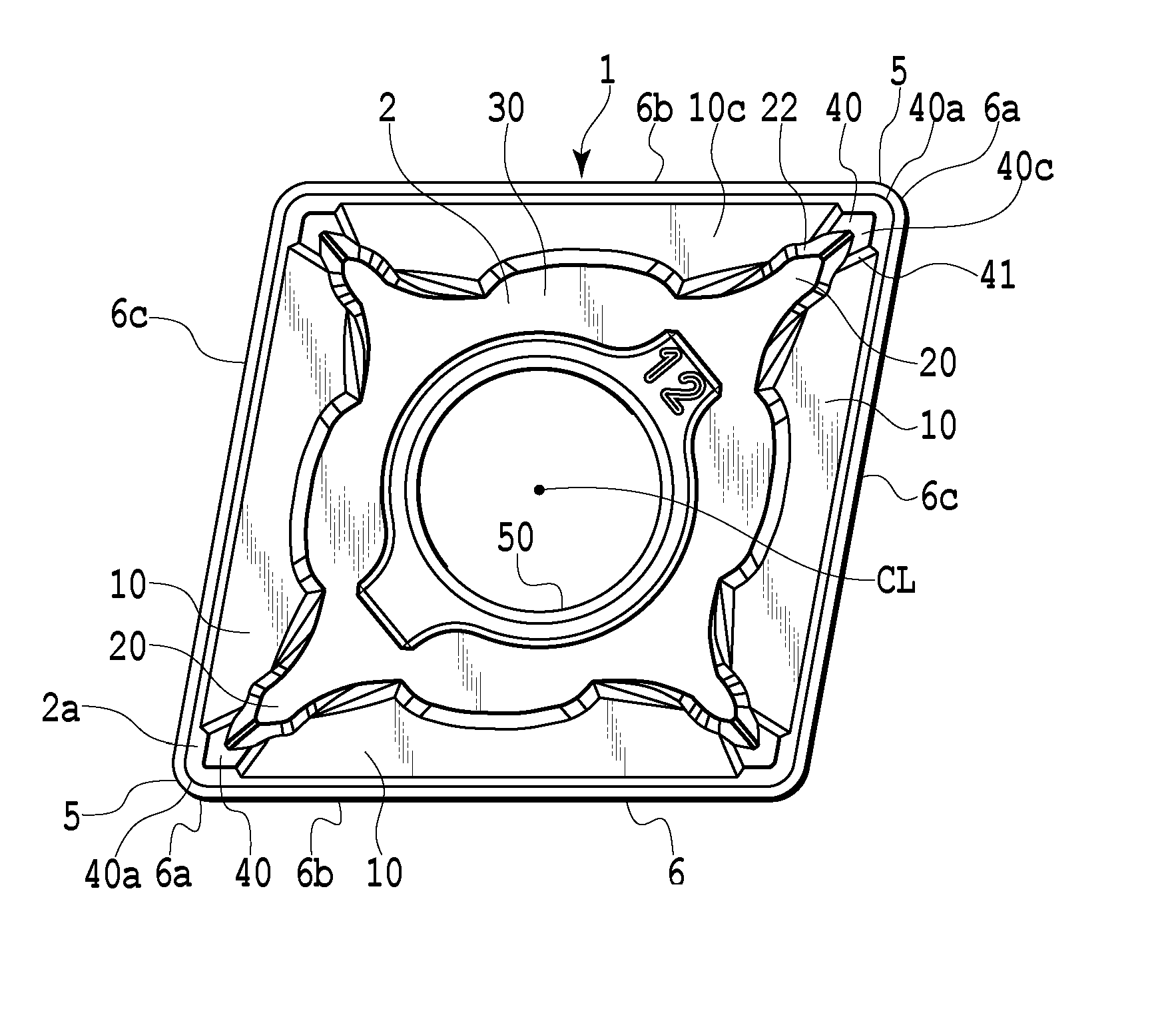
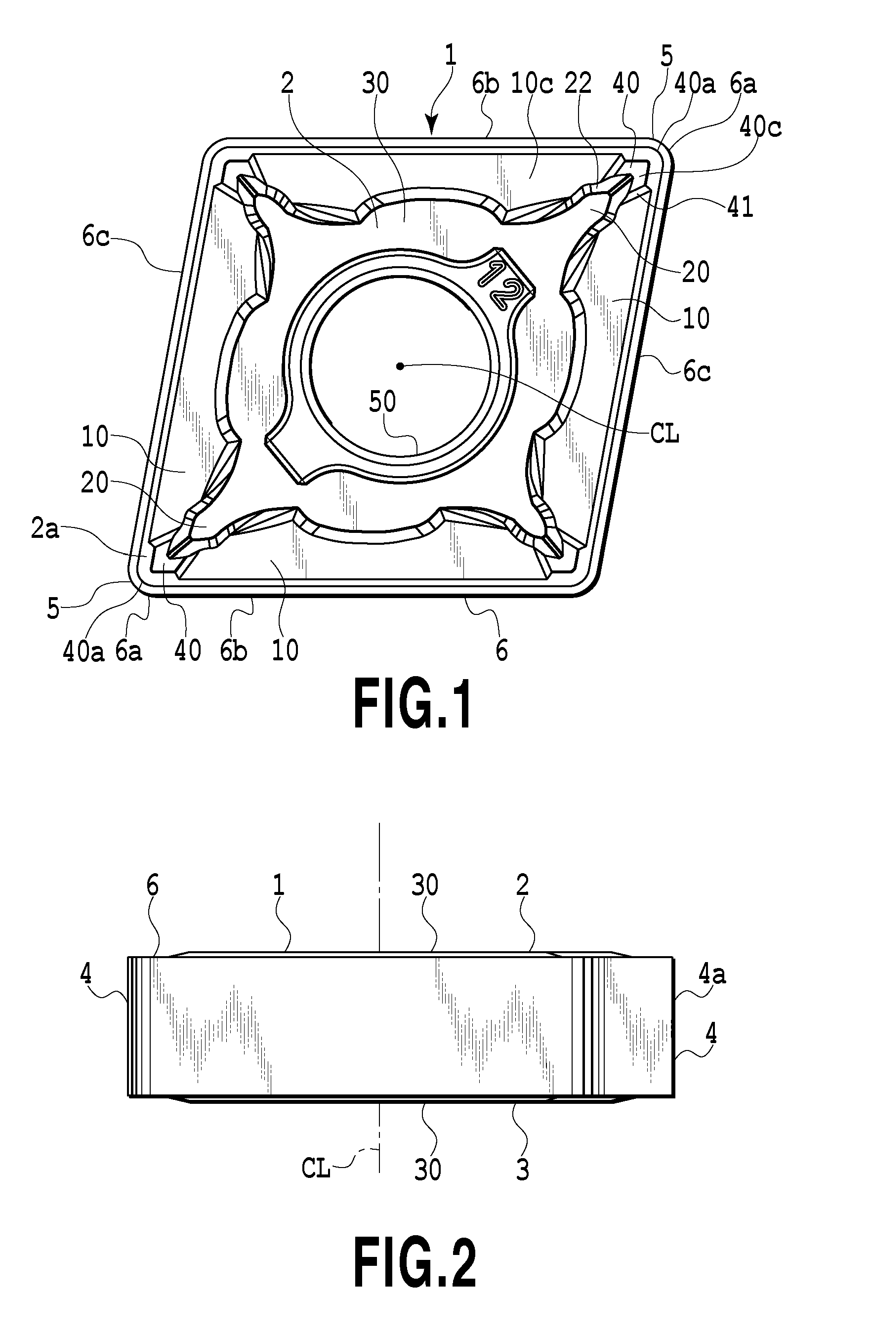
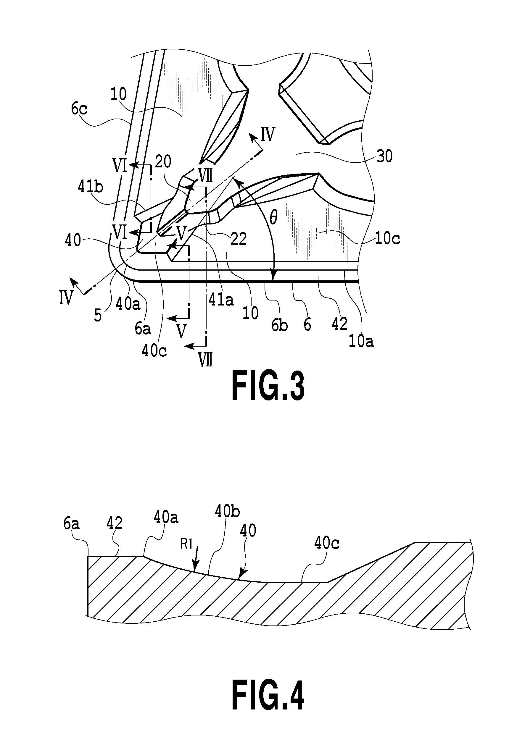
[0027]FIG. 1 is a plan view of a cutting insert which is a first embodiment. FIG. 2 is a front view of the cutting insert illustrated in FIG. 1. FIG. 3 is an enlarged plan view of the vicinity of a nose portion of the cutting insert illustrated in FIG. 1. The cutting insert of the present embodiment has no particular hand, but is symmetric with respect to a bisector B at an apex angle of the nose portion. However, the cutting insert of the present invention is not limited to a cutting insert without particular hand, and the cutting insert described below will be described as an example in which the cutting insert is used as right hand and has a linear cutting edge 6b as a main cutting edge of a working cutting edge in charge of most of the cutting during a cutting work and a linear cutting edge 6c as a sub cutting edge (front cutting edge) of the working cutting edge. Although description will be omitted in the following, if the cutting insert in FIG. 3 is used as left hand converse...


PUM

PropertyMeasurementUnit
relief angleaaaaaaaaaa
angleaaaaaaaaaa
angleaaaaaaaaaa

Abstract

A cutting insert has an approximately polygonal plate shape with a cutting edge formed on a intersection portion between a rake face and a flank. A chip breaker is formed on the rake face, and a chip-breaker concave portion is defined by an inclined surface which is curved in a concave manner and which is smoothly connected to the bottom surface portion while being gradually inclined toward the bottom surface portion, from a peripheral edge portion on a nose portion side to a bottom surface portion.

Description

CROSS-REFERENCE TO RELATED APPLICATIONS[0001]This is a Continuation-in-part of International application No. PCT / JP2011 / 060589, filed 6 May 2011 and published as WO 2011 / 142297A1 on 17 Nov. 2011, which claims the benefit of Japanese Patent Application No. 2010-109587, filed 11 May 2010. The contents of the aforementioned applications are incorporated by references in their entirety.BACKGROUND OF THE INVENTION[0002]1. Field of the Invention[0003]The present invention relates to a cutting insert used for cutting processing of a metal material by being detachably attached to a tool body.[0004]2. Description of the Related Art[0005]A cutting insert disclosed in Japanese Patent Laid-Open No. 2007-175788 has an approximately polygonal plate shape, in which a breaker projection having a standing wall surface which stands upward from a rake face on at least one of its nose portions and also protrudes toward a tip end of the nose portion is formed, and the rake face connected at least to the...

Claims


Application Information

Patent Timeline
Patent Type & Authority Applications(United States)
IPC IPC(8): B23B27/16
CPCB23B27/143Y10T407/23B23B27/1607B23B2200/081B23B2200/201B23B2200/321B23B2200/323B23C2200/081B23C2200/201B23C2200/323B23C2200/326Y10T407/245Y10T407/235Y10T407/24B23B2200/087B23B27/16B23B27/22
Inventor MAJIMA, SHINYA
Owner TUNGALOY CORP
Why Eureka
Try Eureka