Cell module

Active Publication Date: 2013-04-18
PANASONIC INTELLECTUAL PROPERTY MANAGEMENT CO LTD
View PDF5 Cites 46 Cited by
  • Summary
  • Abstract
  • Description
  • Claims
  • Application Information

AI Technical Summary

Benefits of technology

[0012]According to the present disclosure, even when a failure occurs and at least one of the batteries accommodated in the battery module releases gas, the high-temperature gas flowing into the e

Problems solved by technology

In this case, normal batteries affected by the high-te

Method used


Image

  • Cell module
  • Cell module
  • Cell module

Examples


Example

First Embodiment

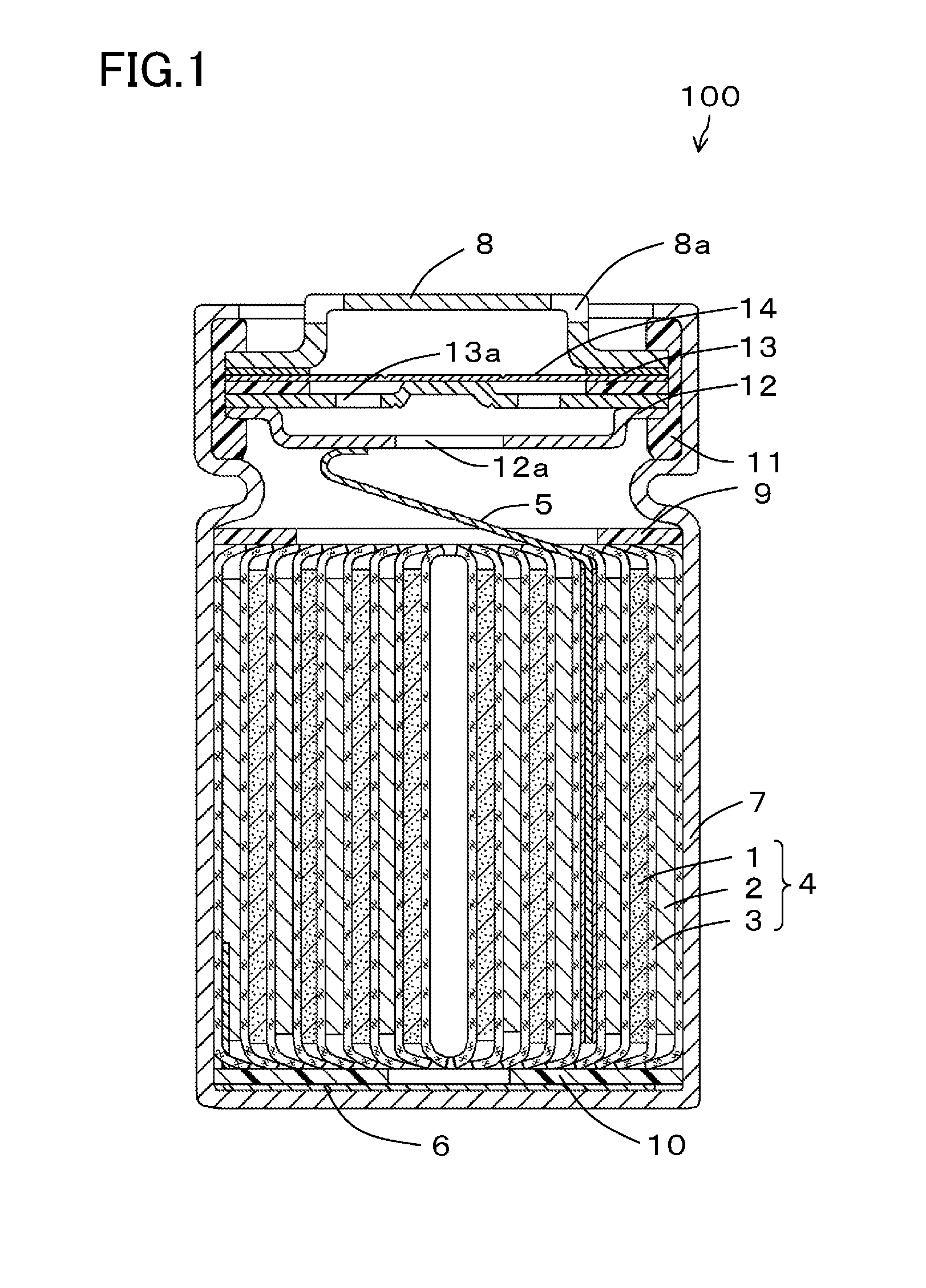
[0025]FIG. 1 is a cross-sectional view schematically illustrating a configuration of a battery 100 to be used in a battery module according to a first embodiment of the present disclosure.

[0026]As the battery 100 to be used in the battery module of this embodiment, for example, a cylindrical lithium ion secondary battery as illustrated in FIG. 1 can be employed. Generally, a lithium ion secondary battery includes a safety mechanism to release gas to outside the battery when the pressure in the battery increases due to occurrence of, for example, an internal short circuit. A specific configuration of the battery 100 will be described below with reference to FIG. 1.

[0027]As illustrated in FIG. 1, an electrode group 4 formed by winding a positive electrode 1 and a negative electrode 2 with a separator 3 interposed between the electrodes 1 and 2 is accommodated in a battery case 7 together with a nonaqueous electrolyte (not shown). Insulating plates 9 and 10 are disposed...


PUM


Abstract

Batteries 100 are accommodated in a case 20, wherein the batteries 100 each include an opening portion 8a for releasing gas produced in an associated one of the batteries to outside the battery, the case 20 is partitioned into an accommodation section 50 configured to accommodate the batteries 100 and an exhaust passage 60 configured to expel the gas released from at least one of the opening portions 8a of the batteries 100 to outside the case 20, the opening portions 8a of the batteries 100 are allowed to communicate with the exhaust passage 60 through sealed connection passages 40, and a one-way open valve 70 which is configured to open only along a direction from the opening portion 8a of the battery 100 to the exhaust passage 60 is provided in an intermediate portion or at an end of each of the connection passages 40.

Description

TECHNICAL FIELD[0001]The present disclosure relates to battery modules including a plurality of batteries accommodated in a case.BACKGROUND ART[0002]Battery packs including a plurality of batteries accommodated in a case to allow an output of a predetermined voltage and capacitance are widely used as power supplies of various devices, vehicles, etc. The technique of forming modules of battery assemblies obtained by connecting general-purpose batteries in parallel and / or in series to output a predetermined voltage and capacitance, and of combining the resultant battery modules together to be applicable to various applications has begun to be adopted. This module forming technique can reduce the size and weight of the battery modules themselves by enhancing the performance of batteries accommodated in the battery modules. Thus, this module forming technique has various advantages: for example, workability in assembling a battery pack can be improved, and the flexibility in mounting ba...

Claims


Application Information

Patent Timeline
IPC IPC(8): H01M2/12H01M50/213H01M50/284
CPCH01M2/1077H01M2/1223H01M2/1241Y02E60/10H01M50/317H01M50/3425H01M50/213H01M50/284H01M50/367H01M50/519
Inventor SHIMIZU, KEISUKEYOKOYAMA, TOMOHIKOFUJIKAWA, MASATONAITO, KEISUKE
Owner PANASONIC INTELLECTUAL PROPERTY MANAGEMENT CO LTD
Why Eureka
Try Eureka