Automated track surveying and ballast replacement

a technology of automatic track surveying and ballast replacement, applied in the direction of process and machine control, instruments, ways, etc., can solve the problems of delay in delivery and loss of income, and achieve the effect of improving the accuracy of the survey

Active Publication Date: 2013-04-18
HERZOG RAILROAD SERVICES
View PDF4 Cites 39 Cited by
  • Summary
  • Abstract
  • Description
  • Claims
  • Application Information

AI Technical Summary

Benefits of technology

[0014]When the survey is complete, the collected data may be processed to refine the position coordinates to enhance the accuracy of the survey. Afterward, the optical scan data is processed to determine the area differences between standard ballast templates and the surveyed ballast profiles. Typically, the ballast profiles are divided into sections representing the area between the rails and left and right shoulder. These sections correspond with inner ballast doors and left and right ballast doors on the ballast hopper cars of the ballast train which will be used for a ballast spreading run. The ballast templates may vary according to particular conditions of the track being surveyed. For example, curved sections of track may be given a different ballast profile than a straight section. Adjacent parallel tracks may be given ballast profiles different from that of a single track. The software used for processing the optical scan data preferably has the capability of enabling an analyst to enter characteristics of particular sections of track so that the correct ballast template is used during processing.
[0015]The area differences may be averaged along a unit length of the track and multiplied by the unit length to derive ballast replacement volumes. The ballast replacement volumes can be converted to ballast replacement unit weights which correspond to geographically specific units of the railway. For example, the unit length may be a hundredth of a mile, and the unit weight may be expressed in units of tons of ballast per hundredth of a mile. The unit weights may be formatted into a ballast replacement data file for a ballast spreading run including left, center, a

Problems solved by technology

Both conventional control methods are so slow as to disrupt normal traffic on the rail

Method used


Image

  • Automated track surveying and ballast replacement
  • Automated track surveying and ballast replacement
  • Automated track surveying and ballast replacement

Examples


Embodiment Construction

[0026]As required, detailed embodiments of the present invention are disclosed herein; however, it is to be understood that the disclosed embodiments are merely exemplary of the invention, which may be embodied in various forms. Therefore, specific structural and functional details disclosed herein are not to be interpreted as limiting, but merely as a basis for the claims and as a representative basis for teaching one skilled in the art to variously employ the present invention in virtually any appropriately detailed structure

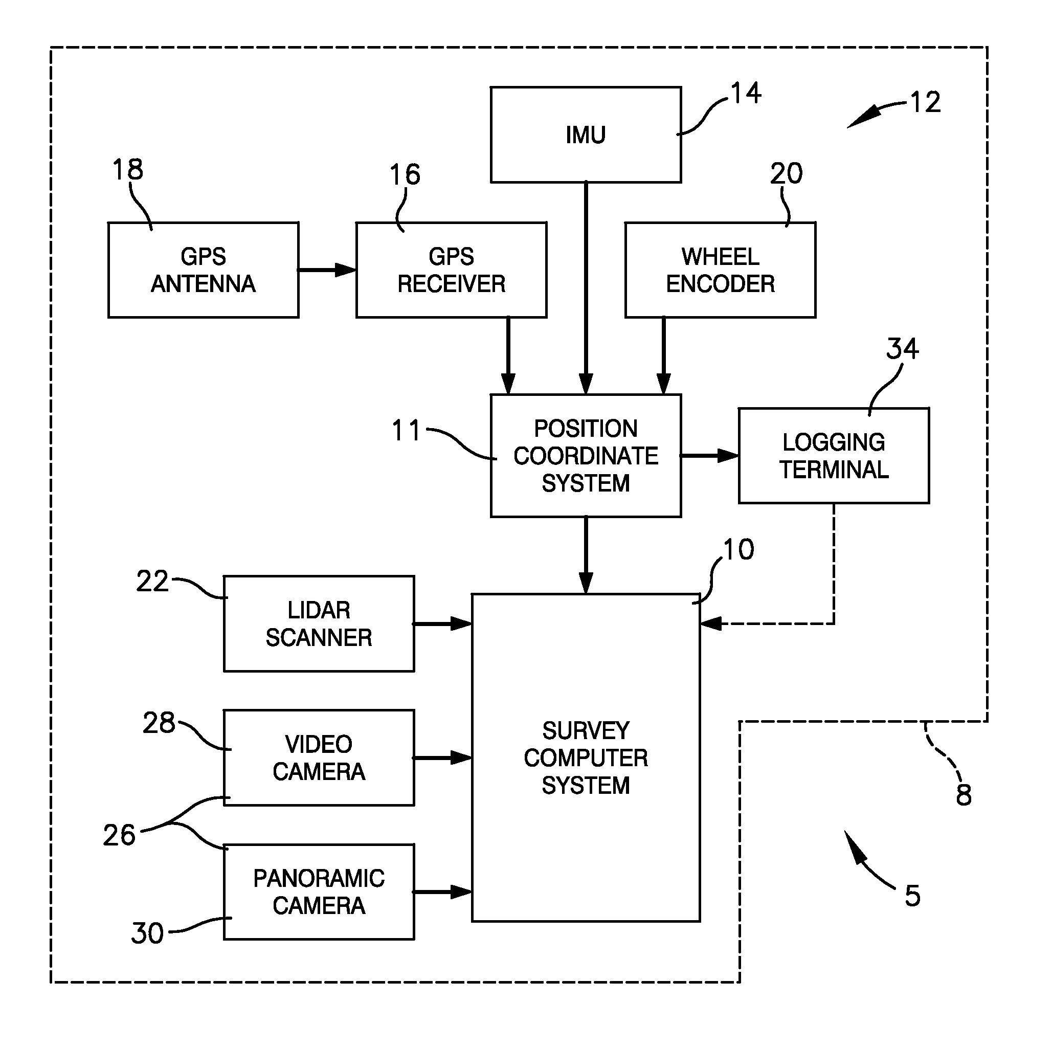
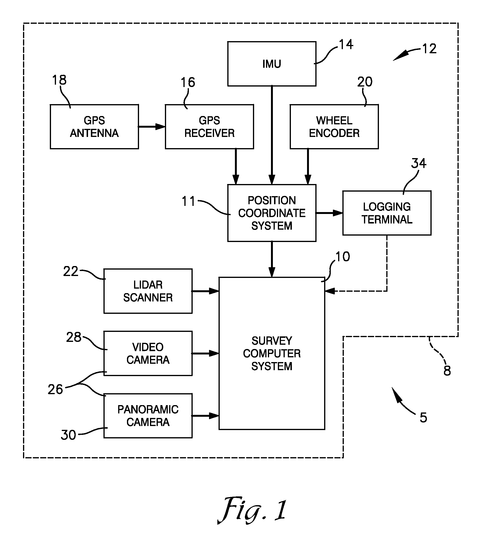
[0027]Referring to the drawings in more detail, the reference number 1 (FIG. 3) generally designates an embodiment of an automated track surveying and ballast replacement method according to the present invention. In general, the method 1 includes automatically surveying a section of a railway to automatically measure and store ballast survey data representing the condition of ballast along the railway section, obtain photographic images, and log position coor...


PUM


Abstract

A method of surveying a section of a railway to determine amounts of ballast to be replaced keyed to position coordinates of track locations includes moving a survey vehicle along the railway, optically scanning the track at selected intervals to obtain optical data points with associated position coordinates, recording images at the intervals with position coordinates, recording position coordinates of no-spread zones, processing the optical data points to derive ballast unit weights associated with locations along the track, detecting anomalous unit weights, accessing images associated with the locations of the anomalous unit weights, accessing the anomalous unit weights to adjust as necessary, and loading the adjusted data into a computer of a ballast train to control the application of replacement ballast along the track according to the detected position of the ballast train.

Description

CROSS-REFERENCE TO RELATED APPLICATION [0001]This application claims priority from U. S. Provisional Application, Ser. No. 61 / 548,429 filed Oct. 18, 2011 for LIDAR BASED AUTOMATED TRACK SURVEYING AND BALLAST REPLACEMENT SYSTEM, the disclosure of which is incorporated herein by reference.BACKGROUND OF THE INVENTION[0002]1. Field of the Invention[0003]This invention relates generally to railroad maintenance and, more particularly, to methods of surveying railroad track beds in conjunction with position recording and performing track maintenance operations, such as ballast replacement, based on the survey results.[0004]2. Background & Description of the Related Art[0005]Conventional railroads in the United States and elsewhere are formed by a compacted sub-grade, a bed of gravel ballast, wooden cross-ties positioned upon and within the ballast, and parallel steel rails secured to the ties. Variations of construction occur at road and bridge crossings, at switch points, and in other cir...

Claims


Application Information

Patent Timeline
IPC IPC(8): E01B27/02G06F19/00
CPCE01B27/02B61K9/00
Inventor LANDES, NATHAN A.BOUNDS, IVAN E.
Owner HERZOG RAILROAD SERVICES
Why Eureka
Try Eureka