This helps you quickly interpret patents by identifying the three key elements:
Problems solved by technology
Method used
Benefits of technology
Benefits of technology
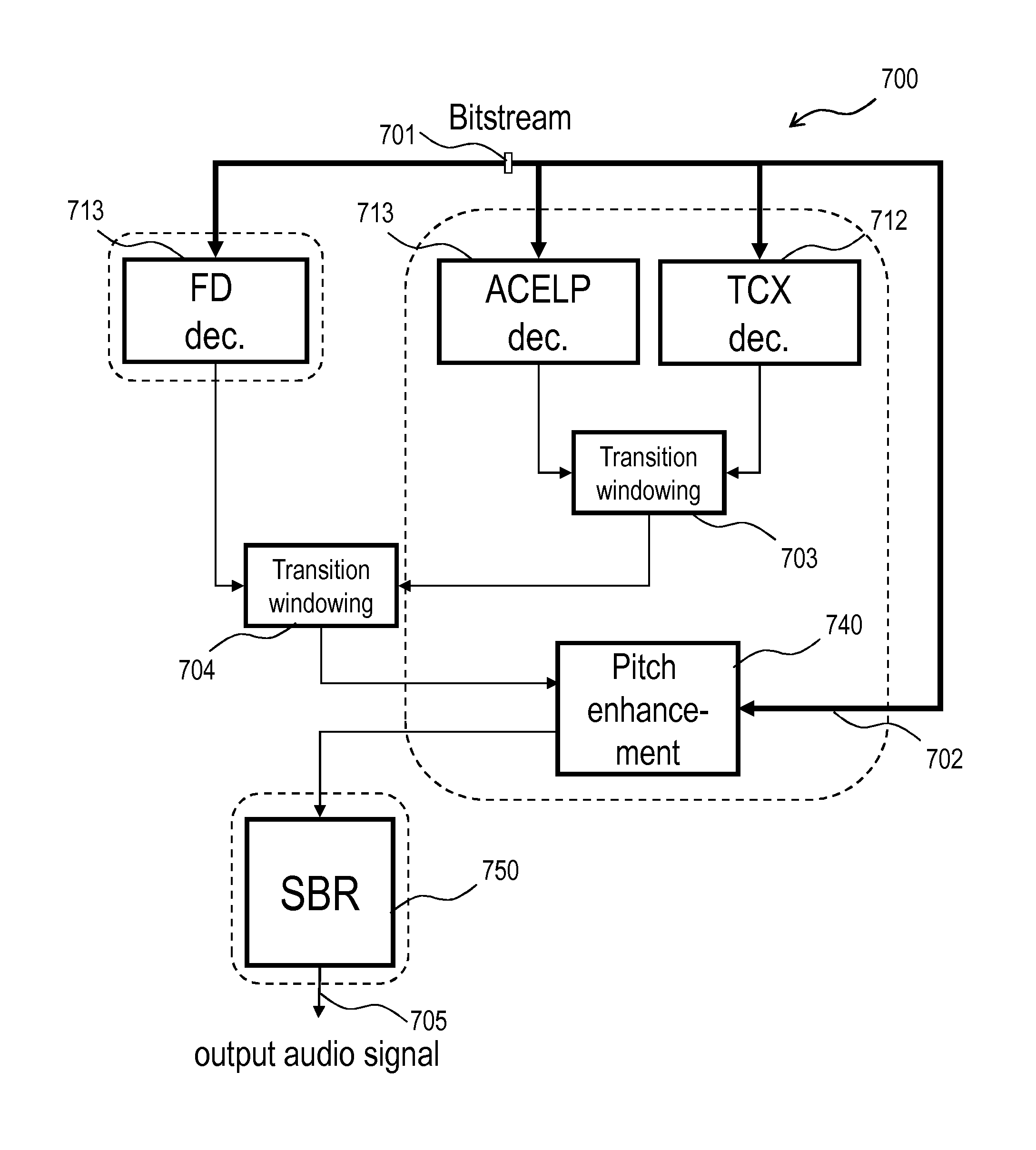
The invention describes an audio encoding method that allows for a separation of decision-making between the use of a post filter and the selection of a preferred coding mode. This helps to maintain consistent post filtering status throughout the duration of the switching process, reducing the likelihood of annoying switch artifacts. The method also allows for the gradual application and removal of post filtering, making the switching between different coding modes less noticeable. Overall, this approach improves the quality and efficiency of audio encoding.
Problems solved by technology
Experiments have confirmed that an alternative solution, or rather circumvention of the problem, by which TCX coding is used throughout (and the ACELP mode is disabled) does not remedy the problem, as reverb-like artefacts appear.
Method used
Image
Click on the blue label to locate the original text in one second.
Reading with bidirectional positioning of images and text.
Examples
embodiment 10
[0084]c) the CELP module is enabled and the post filter is disabled, wherein the preliminary audio time signal and the audio time signal coincide.[0085]12. The decoder system of embodiment 10,
[0086]the decoding section further comprising an Advanced Audio Coding, AAC, decoding module (513; 713) for decoding a bit stream signal as an audio time signal,
[0087]the control section being adapted to operate the decoder also in the following mode:
[0088]d) the AAC module is enabled and the post filter is disabled.[0089]13. The decoder system of embodiment 1, wherein the bit stream signal is segmented into time frames and the control section is adapted to disable an entire time frame or a sequence of entire time frames.[0090]14. The decoder system of embodiment 13, wherein the control section is further adapted to receive, for each time frame in a Moving Pictures Experts Group, MPEG, bit stream, a data field associated with this time frame and is operable, responsive to the value of the data ...
embodiment 26
[0127]c) CELP decoding without post filtering.[0128]27. The method of embodiment 26, wherein the steps of decoding and post-filtering selectively perform one of modes a), b), c) and
[0129]d) Advanced Audio Coding, AAC, decoding.[0130]28. The method of embodiment 20, wherein the bit stream signal is segmented into time frames and the post-filtering step is omitted for an entire time frame or a sequence of entire time frames.[0131]29. The method of embodiment 28, wherein:
[0132]the bit stream signal is a Moving Pictures Experts Group, MPEG, bit stream and includes, for each time frame, an associated data field; and
embodiment 20
[0133]the post-filtering step is omitted in a time frame responsive to the value of the associated data field.[0134]30. The method of embodiment 20, wherein said omission of the post-filtering includes one of the following: full omission of attenuation,
[0135]partial omission of attenuation,
[0136]gradually increasing attenuation, and
[0137]gradually decreasing attenuation.[0138]31. A method of decoding a bit stream signal as an audio time signal, including the steps of:
[0139]decoding a bit stream signal as a preliminary audio time signal; and
[0140]post-filtering the preliminary audio time signal by attenuating interharmonic noise, thereby obtaining an audio time signal,
[0141]characterized in that the step of decoding includes:
[0142]extracting an intermediate decoded signal representing excitation;
[0143]computing an approximate difference signal, which approximates the signal component which is to be removed from the decoded signal by the post filter, as a difference between the interm...
PUM
Abstract
In one aspect, the invention provides an audio encoding method characterized by a decision being made as to whether the device which will decode the resulting bit streamBitstream should apply post filtering including attenuation of interharmonic noise. Hence, the decision whether to use the post filter, which is encoded in the bit stream, is taken separately from the decision as to the most suitable coding mode. In another aspect, there is provided an audio decoding method with a decoding step followed by a post-filtering step, including interharmonic noise attenuation, and being characterized in a step of disabling the post filter in accordance with post filtering information encoded in the bit streamsignal. Such a method is well suited for mixed-origin audio signals by virtue of its capability to deactivate the post filter in dependence of the post filtering information only, hence independently of factors such as the current coding mode.
Description
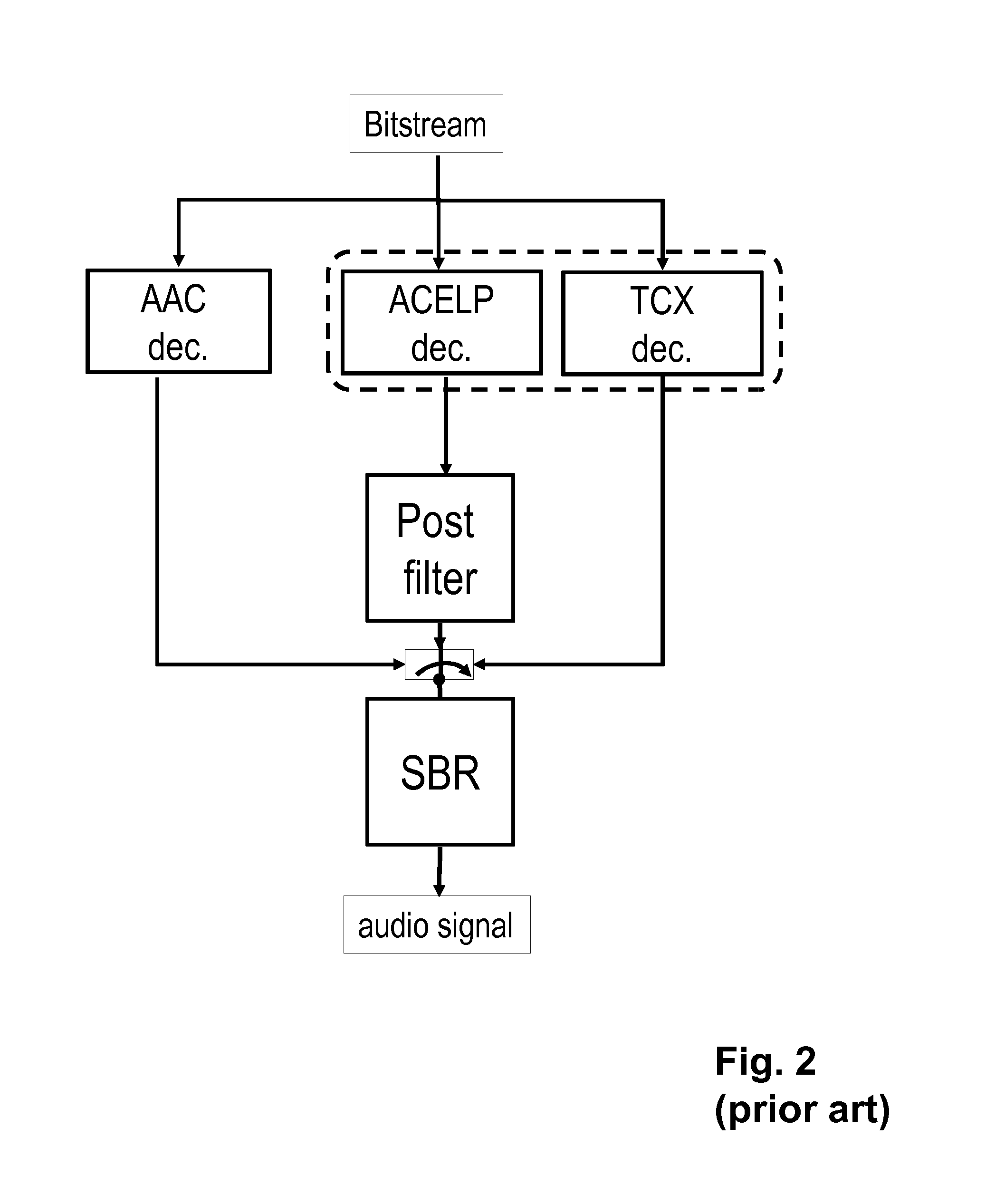
TECHNICAL FIELD[0001]The present invention generally relates to digital audio coding and more precisely to coding techniques for audio signals containing components of different characters.BACKGROUND[0002]A widespread class of coding method for audio signals containing speech or singing includes code excited linear prediction (CELP) applied in time alternation with different coding methods, including frequency-domain coding methods especially adapted for music or methods of a general nature, to account for variations in character between successive time periods of the audio signal. For example, a simplified Moving Pictures Experts Group (MPEG) Unified Speech and Audio Coding (USAC; see standard ISO / IEC 23003-3) decoder is operable in at least three decoding modes, Advanced Audio Coding (AAC; see standard ISO / IEC 13818-7), algebraic CELP (ACELP) and transform-coded excitation (TCX), as shown in the upper portion of accompanying FIG. 2.[0003]The various embodiments of CELP are adapted...
Claims
Application Information
Patent Timeline
Application Date:The date an application was filed.
Publication Date:The date a patent or application was officially published.
First Publication Date:The earliest publication date of a patent with the same application number.
Issue Date:Publication date of the patent grant document.
PCT Entry Date:The Entry date of PCT National Phase.
Estimated Expiry Date:The statutory expiry date of a patent right according to the Patent Law, and it is the longest term of protection that the patent right can achieve without the termination of the patent right due to other reasons(Term extension factor has been taken into account ).
Invalid Date:Actual expiry date is based on effective date or publication date of legal transaction data of invalid patent.

