Vibration power generator, vibration power generation apparatus, and electric device and communication device with vibration power generation apparatus mounted thereon

a technology of vibration power generator and power generation apparatus, which is applied in the direction of electrostatic generator/motor, influence generator, electrical apparatus, etc., can solve the problems of difficult to reduce the spring constant, difficult to make the resonance frequency lower, and the inability to use the spring b>19/b> for a long tim

Active Publication Date: 2013-04-25
PANASONIC CORP
View PDF1 Cites 9 Cited by
  • Summary
  • Abstract
  • Description
  • Claims
  • Application Information

AI Technical Summary

Benefits of technology

[0032]The vibration power generator according to the embodiments of the present invention can use an electrostatic force as a restoring force of a spring to thereby solve the problem of durability, such as fatigue breakdown due to the repetition of use, which might be caused in the case of using a mechanical spring. Further, the vibration power generator according to the embodiments of the present invention can cause the first substrate to vibrate at a large amplitude even upon receiving the external vibration at a low frequency, for example, of about several Hz. Accordingly, the vibration power generator can generate power using the vibration in the low frequency range in the environment.

Problems solved by technology

In the vibration power generator 10, however, the resonance frequency is determined depending on the states of the first substrate 11 and the spring 19, which disadvantageously makes it difficult to make the resonance frequency lower.
The spring 19 is normally formed of silicon or the like, which makes it difficult to decrease the spring constant of the spring 19 due to restrictions on the elastic constant of material or the size of the spring.
As a result, the spring 19 cannot be used for a long time.
This leads to problems of insufficient durability and reliability of the vibration power generator 10.

Method used


Image

  • Vibration power generator, vibration power generation apparatus, and electric device and communication device with vibration power generation apparatus mounted thereon
  • Vibration power generator, vibration power generation apparatus, and electric device and communication device with vibration power generation apparatus mounted thereon
  • Vibration power generator, vibration power generation apparatus, and electric device and communication device with vibration power generation apparatus mounted thereon

Examples


first embodiment

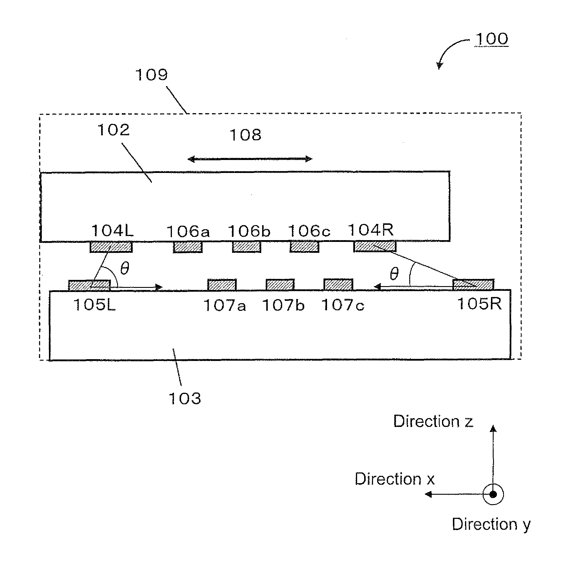
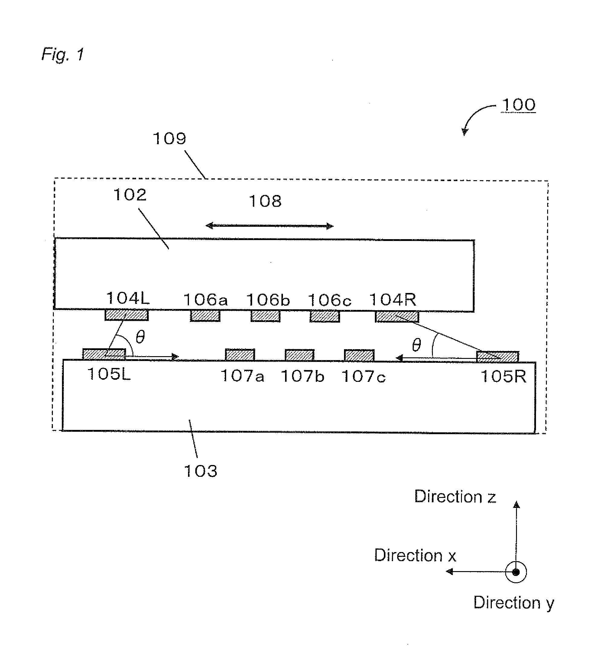
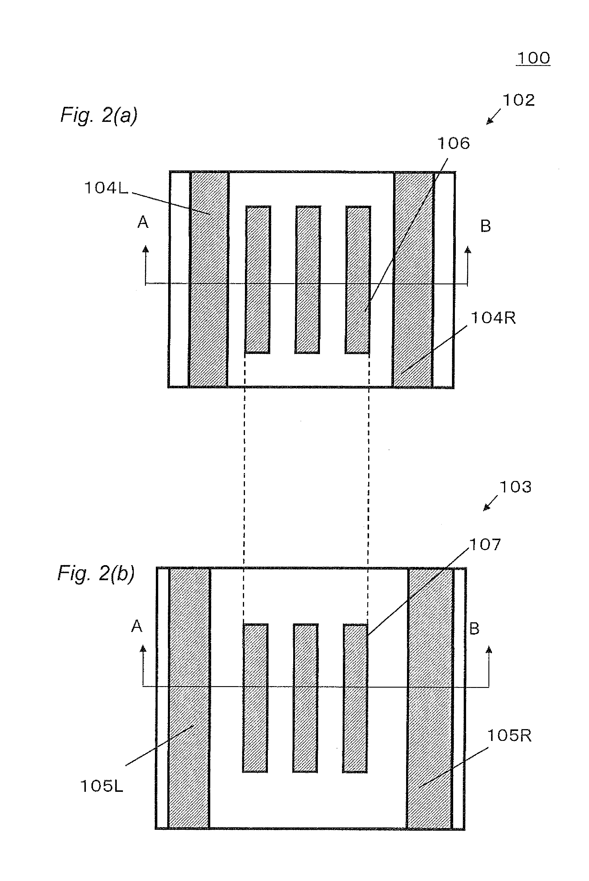
[0104]FIG. 1 is a cross-sectional view of a vibration power generator 100 in a first embodiment. FIG. 2(a) and FIG. 2(b) are plan views of a first substrate and a second substrate of the vibration power generator 100 shown in FIG. 1. The cross-section shown in FIG. 1 corresponds to the cross-section taken along the line A-B of FIG. 2.

[0105]The vibration power generator 100 comprises a first substrate 102 and a second substrate 103. The first substrate 102 and the second substrate 103 each are comprised of a Si substrate. The first substrate 102 and the second substrate 103 have respective substrate surfaces (each corresponding to a main surface at which an electrode is formed) which are opposed to each other with a certain distance. The first substrate 102 is kept floating in air. The second substrate 103 is fixed (not shown). Third electrodes 104L and 104R are formed over the first substrate 102. Fourth electrodes 104L and 104R are formed over the second substrate 103. The third el...

second embodiment

[0150]FIG. 7 is a cross-sectional view (cross-sectional view taken along the vibrational direction 308 of the first substrate 302) of a vibration power generator 300 in the second embodiment. The second embodiment differs from the first embodiment in the following points.

[0151]Fixed structures 314L, and 314R are formed over a substrate surface of a second substrate 303.

[0152]First stoppers 313L and 313R are formed over both sides of the first substrate 302, and second stoppers 315L and 315R are formed over the fixed structures 314L and 314R so as to be capable of contacting with the first stoppers 313L, and 313R. The first stoppers 313L and 313R, and the second stoppers 315L and 315R restrict the amplitude of the vibration of the first substrate 302 to prevent the increase in amount of displacement of the first substrate 302, as will be described later. In the embodiment shown, the first stoppers 313L and 313R, and the second stoppers 315L and 315R are positioned on a line that is i...

third embodiment

[0169]FIG. 15 is a cross-sectional view of a vibration power generator 600 according to a third embodiment. FIGS. 16(a) and 16(b) are plan views of a first substrate and a second substrate of the vibration power generator 600 shown in FIG. 15, respectively. The cross-section shown in FIG. 15 corresponds to the cross-section taken along the line A-B of FIG. 16.

[0170]This embodiment differs from the first embodiment in that fifth electrodes 609L and 609R are formed over a second substrate 603. In FIG. 15, the same member or element as that shown in FIG. 1 is designated by reference numeral of 6 in hundreds place with the same digits on tens and ones places as those shown in FIG. 1. As shown in FIG. 15, a fifth electrodes 609L (609R) is formed on the center side of the second substrate as compared to the fourth electrode 605L (605R).

[0171]The fifth electrode 609L holds the charge of the same polarity as that of the charge held by the third electrode 604L and the fourth electrode 605L. ...


PUM


Abstract

A power generator comprises a first substrate 102, a second substrate 103 opposed to the first substrate, first electrodes 104L and 104R and a first electrode 106 which are formed on the first substrate, second electrodes 105L and 105R and a second electrode 107 which are formed on the second substrate, wherein electric charge of the same polarity is held by the first electrode and the second electrode, and the first substrate vibrates such that an angle formed between a segment connecting a centroid of the first electrode 104L (104R) and a centroid of the second electrode 105L (105R), and a half line extending from the centroid of the second electrode 105L (105R) toward the first electrode 104L (104R) in a stationary state in parallel to the main surface of the second substrate does not exceed 55 degrees while the first substrate 102 is stationary and vibrates.

Description

TECHNICAL FIELD[0001]The present invention relates to vibration power generators, and more specifically, to an electrostatic vibration power generator using an electret.BACKGROUND ART[0002]As a conventional vibration power generator, an electrostatic induction vibration power generation apparatus is known in which an electric charge is applied to one electrode of a variable capacity and the electric charge is induced to another opposed electrode through electrostatic induction. The electric charge to be induced is varied by changing of the capacity. The electrostatic vibration power generation apparatus serves to generate power by taking out the change in the electric charge as electric energy (see Patent Document 1).[0003]FIG. 24 is a schematic cross-sectional view showing a conventional electrostatic vibration power generator disclosed in Patent Document 1, specifically, a vibration power generator 10 using electret material.[0004]The vibration power generator 10 includes a first ...

Claims


Application Information

Patent Timeline
Patent Type & Authority Applications(United States)
IPC IPC(8): H02N1/08
CPCH02N1/08
Inventor TAKEUCHI, HIROKINAKATSUKA, HIROSHIONISHI, KEIJI
Owner PANASONIC CORP
Why Eureka
Try Eureka