Method and Apparatus for Radome and Reflector Dish Interconnection

a technology of radome and reflector, which is applied in the field of microwave reflector antennas, can solve the problems of limiting interchangeability and/or replacement, increasing the total number of discrete components, and requiring additional threading/tightening assembly steps,

Inactive Publication Date: 2013-04-25
COMMSCOPE TECH LLC
View PDF5 Cites 15 Cited by
  • Summary
  • Abstract
  • Description
  • Claims
  • Application Information

AI Technical Summary

Problems solved by technology

Because reflector antennas are often mounted in remote locations, such as high atop radio towers, a radome failure may incur significant repair/replacement expense.
However, nut and bolt closures may loosen with time, increase the total number of disc

Method used


Image

  • Method and Apparatus for Radome and Reflector Dish Interconnection
  • Method and Apparatus for Radome and Reflector Dish Interconnection
  • Method and Apparatus for Radome and Reflector Dish Interconnection

Examples


Embodiment Construction

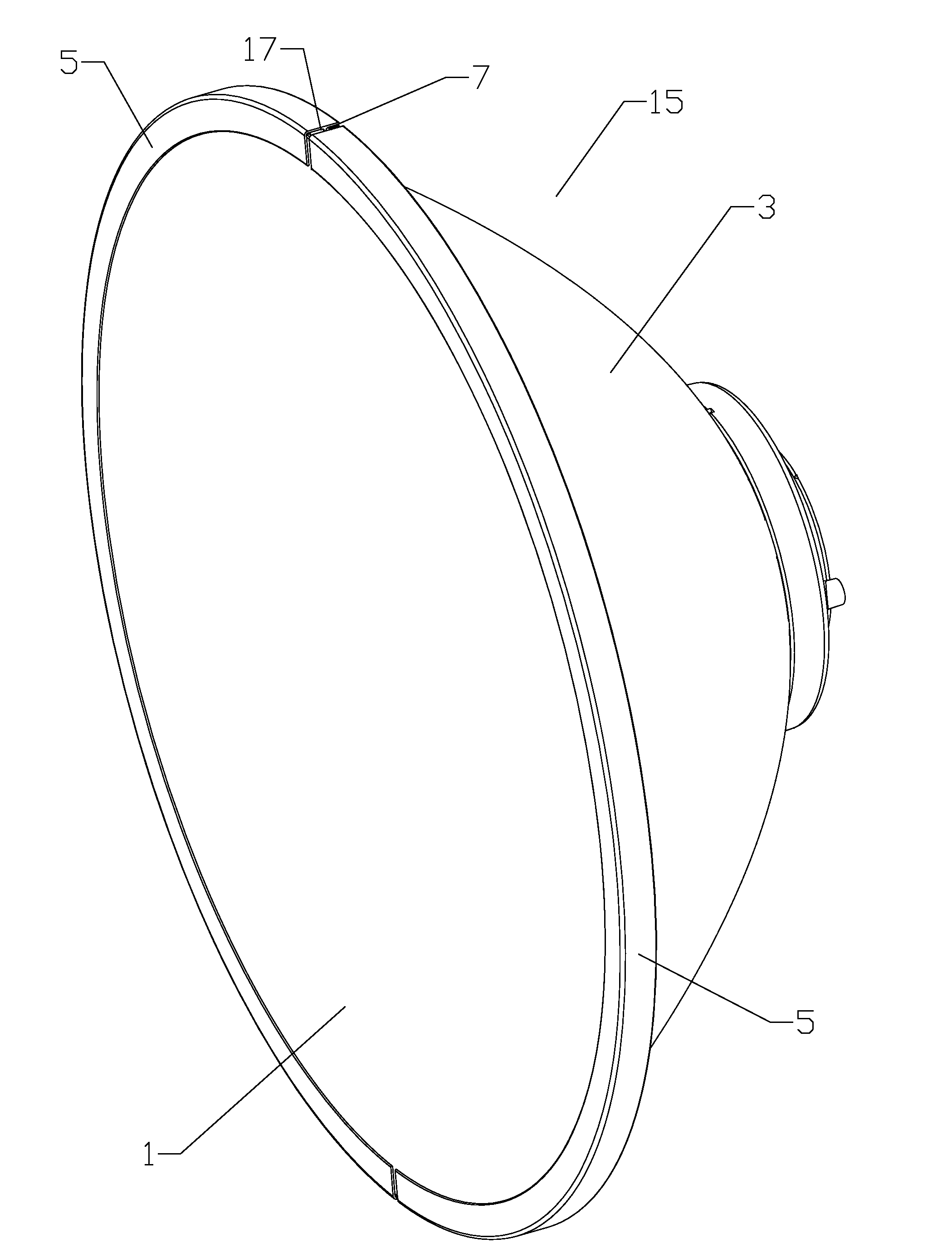
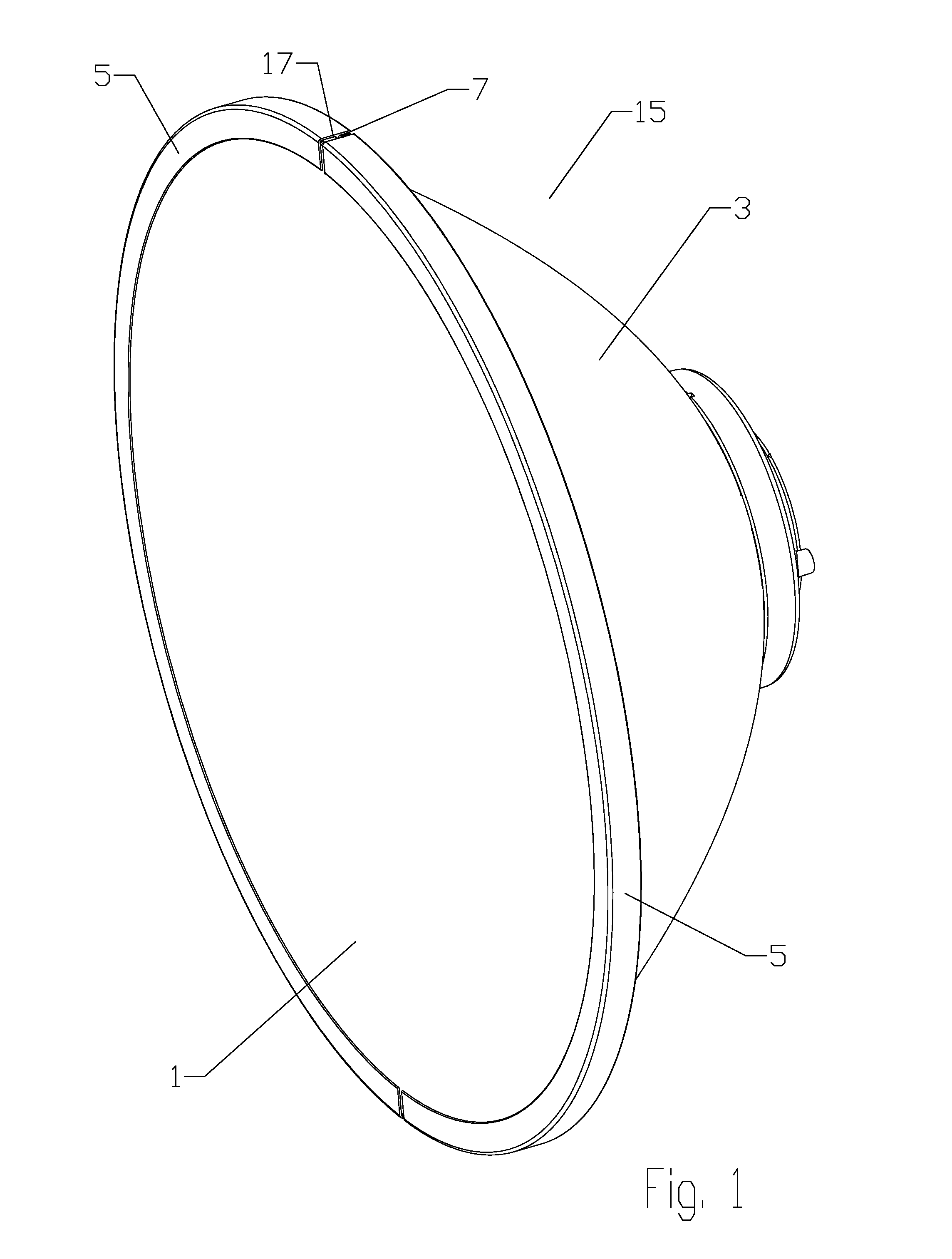
[0015]A radome 1 is retained on reflector dish 3 via a permanent band clamp type interconnection that may be cost efficiently formed by crimping a plurality of curved channel portions 5 end to end around a shared link member 7, for example as shown in FIG. 1. Thereby, a reliable permanent interconnection may be cost efficiently formed from a minimum number of simplified parts, which may enable significant materials, manufacturing and / or installation efficiencies.

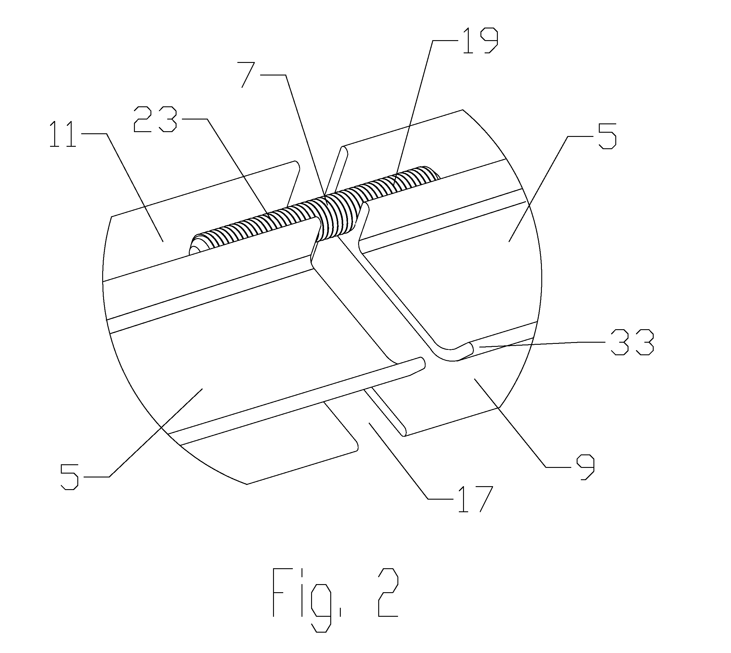
[0016]As best shown in FIGS. 2-5, the channel portions 5 are provided with an open periphery slot 9 and an open retention slot 11. The periphery slot 9 is dimensioned to receive the periphery of the radome 1 and the periphery of the reflector dish 3 seated upon one another. The channel portions 5 are arranged end-to-end adjacent to one another, encircling the periphery of the radome 1 and the periphery of the reflector dish 3 seated within the periphery slot 9. A gap 17 may be provided between each channel portions 5 are arr...


PUM

PropertyMeasurementUnit
Diameteraaaaaaaaaa

Abstract

An interconnection retaining a radome upon a periphery of a reflector dish has a plurality of curved channel portions, each of the channel portions provided with an open periphery slot and an open retention slot. The periphery slot dimensioned to receive the peripheries of the radome and reflector dish. The channel portions are arranged end-to-end adjacent to one another, encircling the peripheries of the radome and reflector dish seated within the periphery slot. A gap may be provided between one or more of the channel portions. A link member is seated within the retention slot at an end of each adjacent channel portion. The retention slot at the end of each of the adjacent channel portions is crimped upon the link member. The link member may be, for example, a portion of threaded rod or a molded portion of polymer material.

Description

BACKGROUND[0001]1. Field of the Invention[0002]This invention relates to microwave reflector antennas. More particularly, the invention relates to a cost-efficient radome bandclamp-type interconnection for retaining a radome upon the periphery of the reflector dish of a microwave reflector antenna.[0003]2. Description of Related Art[0004]The open end of a reflector antenna is typically enclosed by a radome coupled to the distal end (the open end) of the reflector dish. The radome provides environmental protection and improves wind load characteristics of the antenna. Because reflector antennas are often mounted in remote locations, such as high atop radio towers, a radome failure may incur significant repair / replacement expense.[0005]A band clamp may be applied to retain the radome upon the reflector dish periphery via a removable closure means, such as a nut and bolt. However, nut and bolt closures may loosen with time, increase the total number of discrete components and / or requir...

Claims


Application Information

Patent Timeline
IPC IPC(8): H01Q19/12B23P11/00
CPCH01Q19/12B23P11/005Y10T29/49908H01Q1/42H01Q1/12H01Q15/16Y10T403/49
Inventor WRIGHT, ALASTAIR D.RENILSON, IANCURRAN, JOHN S.LEWRY, MATTHEW R.
Owner COMMSCOPE TECH LLC
Why Eureka
Try Eureka