Antenna module

a technology of antenna modules and antenna modules, applied in the direction of antennas, antenna details, antenna couplings, etc., can solve the problems of inability to optimize the performance difficult design, and large size of the antenna module, so as to achieve stable radiation pattern, reduce the volume of the antenna module and the electronic device, and reduce the effect of volum

Active Publication Date: 2013-04-25
LYNWAVE TECH
View PDF1 Cites 9 Cited by
  • Summary
  • Abstract
  • Description
  • Claims
  • Application Information

AI Technical Summary

Benefits of technology

[0011]According to the structure of the antenna module in the disclosure, two radiation portions are provided and antennas are arranged in all directions to transmit signals, so that the volume of the antenna module and the electronic device can be greatly reduced, and the stable radiation pattern and broadband and multi-band requirements can be met.

Problems solved by technology

However, as communication apparatuses become lighter, thinner, shorter, and smaller, the size of the antenna module also needs to be gradually reduced, resulting in the incapability of optimizing the performance of the antenna module.
In order to solve the above problem, in the prior art, multiple antennas must be arranged in a communication apparatus with limited volume, which is difficult to design.
Alternatively, the antenna module is manufactured outside the communication apparatus, which largely increases the volume of the radio transceiver device and does not meet the light and thin requirements of the modern communication apparatus.
On the contrary, to install the antenna module in a miniature communication apparatus and maintain the antenna performance as well, the volume of the antenna module must be limited to a certain size, and thus the operation band of the antenna module is limited, or a radiation pattern of poor stability is caused.

Method used


Image

  • Antenna module
  • Antenna module
  • Antenna module

Examples


first embodiment

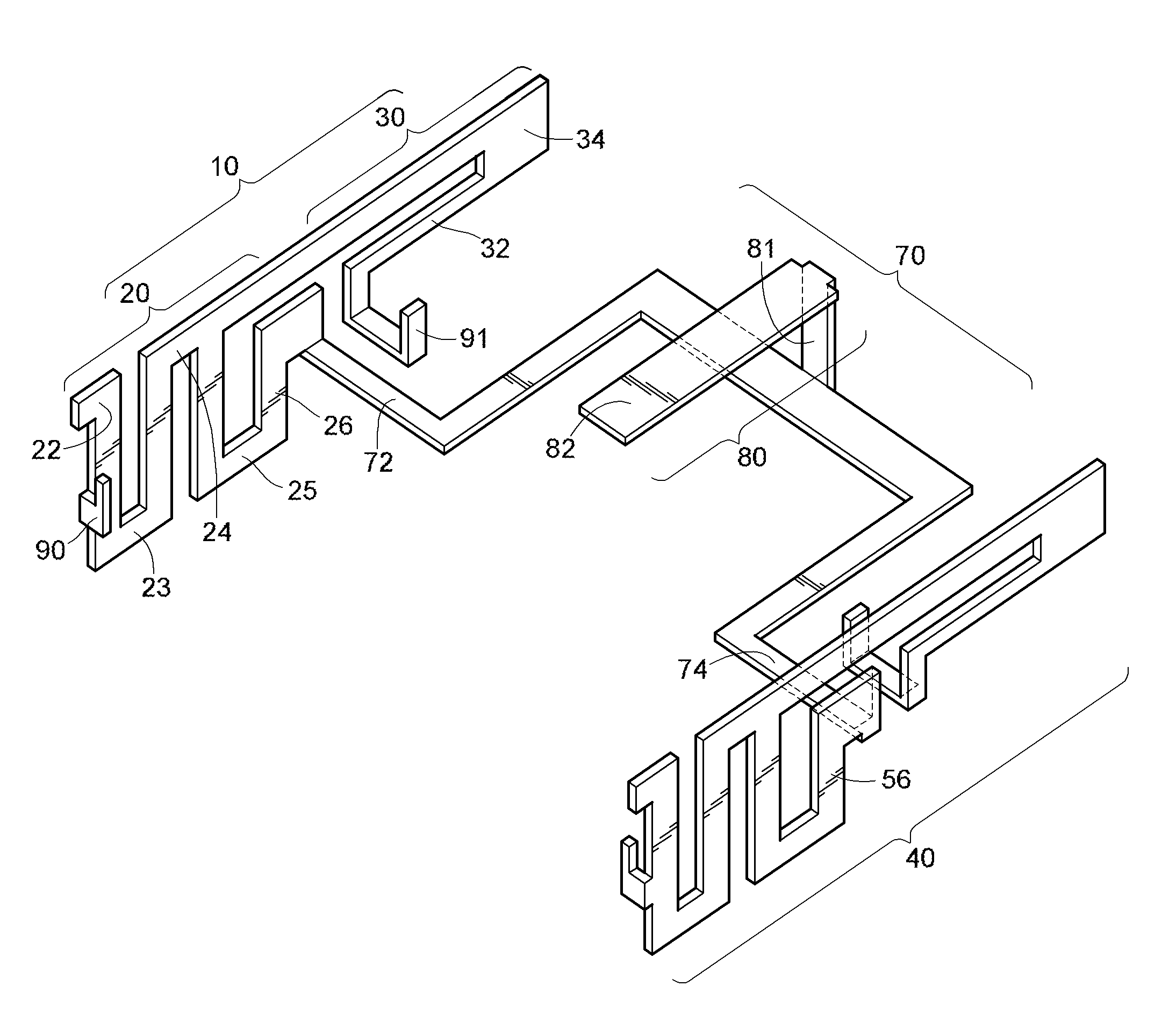
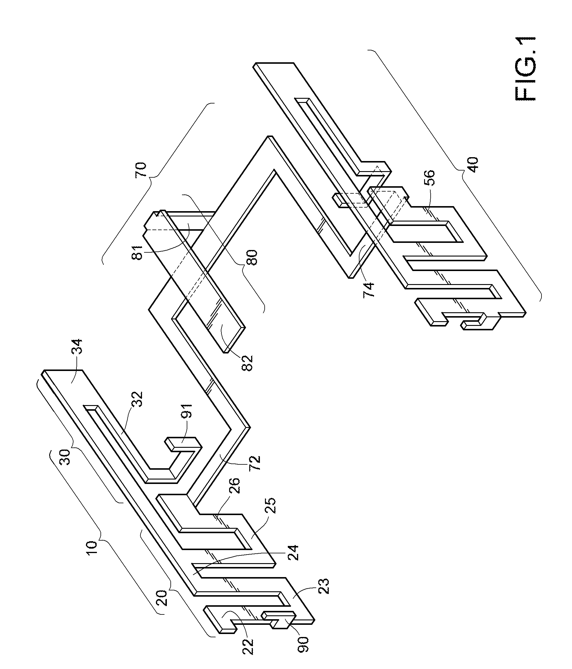
[0017]FIG. 1 is a schematic structural view of an antenna module according to the disclosure. The structure shown in this figure is formed of a piece of conductive material, for example, metal. For the convenience of description, the antenna module is disassembled into a plurality of components.

[0018]The antenna module according to the first embodiment of the disclosure comprises a first antenna 10, a second antenna 40, a grounding portion 70, and an isolation metal sheet 80. The first antenna 10 comprises a first radiation portion 20 and a second radiation portion 30. An overall structure of the second antenna 40 is the same as that of the first antenna 10, so the reference numbers of structures in the second antenna 40 are omitted and replaced with those of the first antenna 10. Therefore, the first embodiment of the disclosure is described mainly by taking an example that the first antenna 10 is disassembled into a plurality of components. The grounding portion 70 of the antenna ...

second embodiment

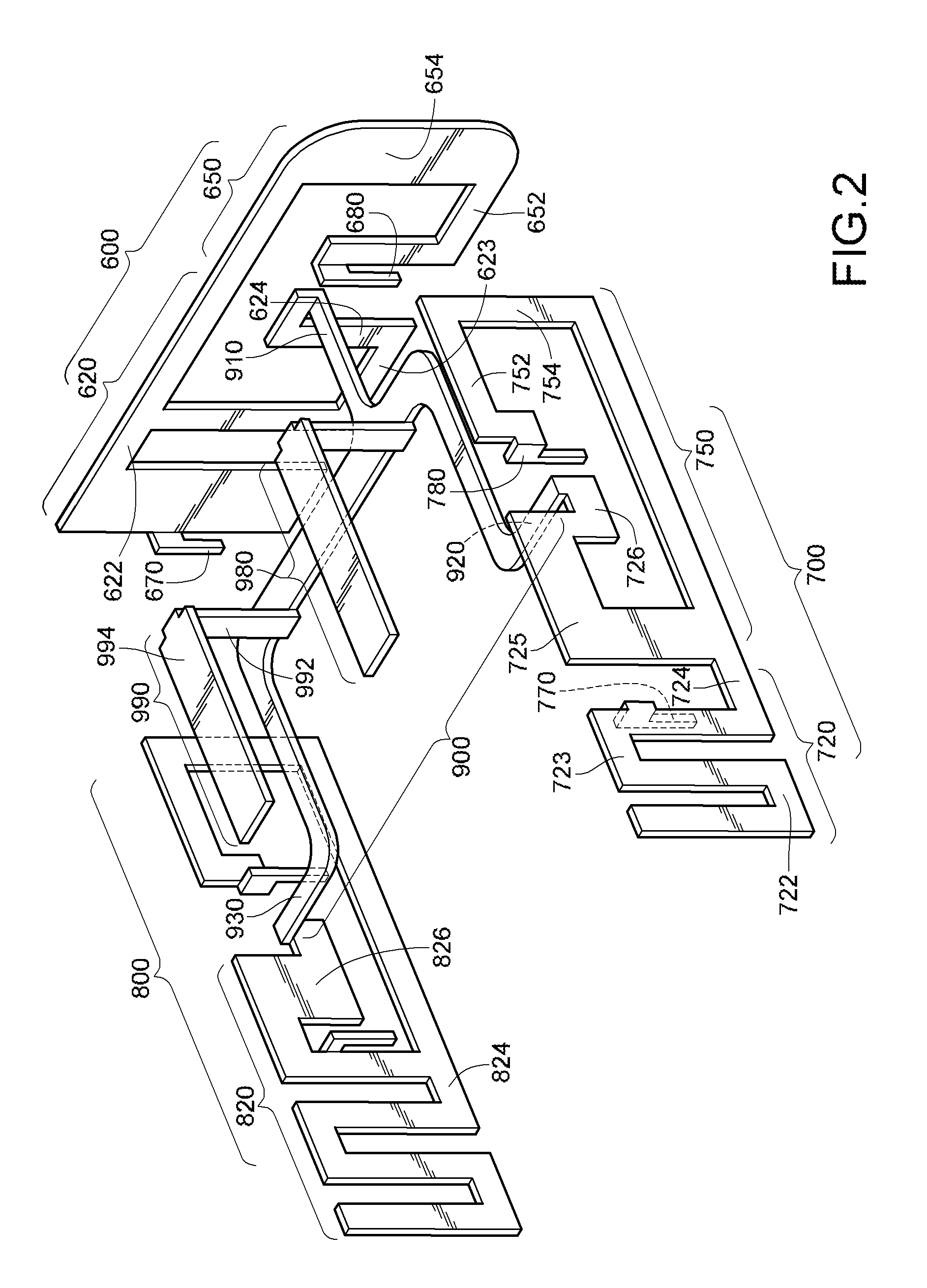
[0020]FIG. 2 is a schematic structural view of an antenna module according to the disclosure. The structure shown in this figure is integrally formed of a conductive material, for example, metal. For the convenience of description, the antenna module is disassembled into a plurality of components for description.

[0021]The antenna module according to the second embodiment of the disclosure comprises a first antenna 600, a second antenna 700, a third antenna 800, a grounding portion 900, a first isolation metal sheet 980, and a second isolation metal sheet 990. The first antenna 600 comprises a first radiation portion 620 and a second radiation portion 650, and the second antenna 700 comprises a first radiation portion 720 and a second radiation portion 750. In this embodiment, an overall structure of the third antenna 800 is similar to that of the second antenna 700, so that most of reference numbers of the third antenna 800 are omitted. Therefore, this embodiment of the disclosure i...

third embodiment

[0025]FIG. 3 is a schematic structural view of an antenna module according to the disclosure. The structure shown in this figure is integrally formed of a conductive material, for example, metal. For the convenience of description, an antenna is disassembled into a plurality of components for description.

[0026]The antenna module according to the third embodiment of the disclosure comprises a first antenna 100, a second antenna 200, a third antenna 300, a grounding portion 400, a first isolation metal sheet 520, a second isolation metal sheet 540, and a third isolation metal sheet 560. The first antenna 100 comprises a first radiation portion 120 and a second radiation portion 150, and the second antenna 200 comprises a first radiation portion 220 and a second radiation portion 250. An overall structure of the third antenna 300 is the same as that of the second antenna 200, so that most of reference numbers of the third antenna 300 are omitted. Therefore, this embodiment of the discl...


PUM


Abstract

An antenna module mainly includes at least one antenna capable of radiating signals of two frequencies, a grounding portion, and at least one isolation metal sheet capable of isolating signals of a frequency generated by different antennas from each other to avoid interference. The antenna module is integrally formed, which can reduce the volume of the antenna module, and provide a stable radiation pattern and broadband and multi-band functions.

Description

CROSS-REFERENCE TO RELATED APPLICATIONS[0001]This non-provisional application claims priority under 35 U.S.C. §119(a) on Patent Application No(s). 100219607 filed in Taiwan, R.O.C. on Oct. 19, 2011, the entire contents of which are hereby incorporated by reference.BACKGROUND[0002]1. Technical Field[0003]The disclosure relates to an antenna module, and more particularly to a broadband and multi-band antenna module having a stable radiation pattern.[0004]2. Related Art[0005]To connect to wireless local area network, a computer device must be electrically connected to a radio transceiver device. An electrical connection portion of the radio transceiver device generally meets the standard specification of a Universal Serial Bus (USB), and can be electrically connected to a USB port of the computer device. Therefore, at least one antenna module for receiving and transmitting radio signals needs to be built in the radio transceiver device, and preferably, the antenna module is a broadband...

Claims


Application Information

Patent Timeline
Patent Type & Authority Applications(United States)
IPC IPC(8): H01Q1/52
CPCH01Q21/30H01Q1/521H01Q21/28
Inventor WU, SAN-YUAN
Owner LYNWAVE TECH
Why Eureka
Try Eureka