
Aperture System for Multi-Angle Light Scattering Detectors

a detector and aperture system technology, applied in the direction of scattering properties measurement, measurement devices, sampling, etc., can solve the problems of vibration, instabilities and overdrives of detector signals, distorting measurements, and inability to stabilize the remission, so as to minimize angle falsification or scattering of light on the optical transition

Active Publication Date: 2013-04-25
POSTNOVA ANALYTICS
View PDF9 Cites 6 Cited by
  • Summary
  • Abstract
  • Description
  • Claims
  • Application Information

AI Technical Summary

Benefits of technology

The invention is a device for measuring the scattering of light from multiple angles in a small range using a translucent cell filled with a sample or through which the sample flows. The device uses a laser beam to illuminate the sample, and measures the scattered light from different angles. The device overcomes the issues of previous devices with non-observed angle ranges and remissions, and improves measuring sensitivity.

Problems solved by technology

However, when using the glass measuring cells described in WO 2010 / 036736 for the measurement of static multi-angle light scattering within an angle range of less than 7° to above 164° the following problems occur.
Due to minimal laser position fluctuations, the remissions are not stable and lead to vibrations, instabilities and overdrives in the detector signals when they reach the detectors.
The problem here is that light within these bore holes is reflected on the respective wall and so, even if in reduced form, can fall into individual detectors and distort the measurements.
Since the bore holes on the one hand must have a small diameter, but on the other hand must be relatively long in order to be able to restrict the angle range of the incident scattered light sufficiently, it is not possible to coat the inside of the bore holes homogeneously with a light-absorbing substance.

Method used


Image

  • Aperture System for Multi-Angle Light Scattering Detectors
  • Aperture System for Multi-Angle Light Scattering Detectors
  • Aperture System for Multi-Angle Light Scattering Detectors

Examples


Embodiment Construction

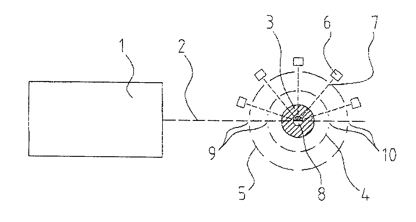
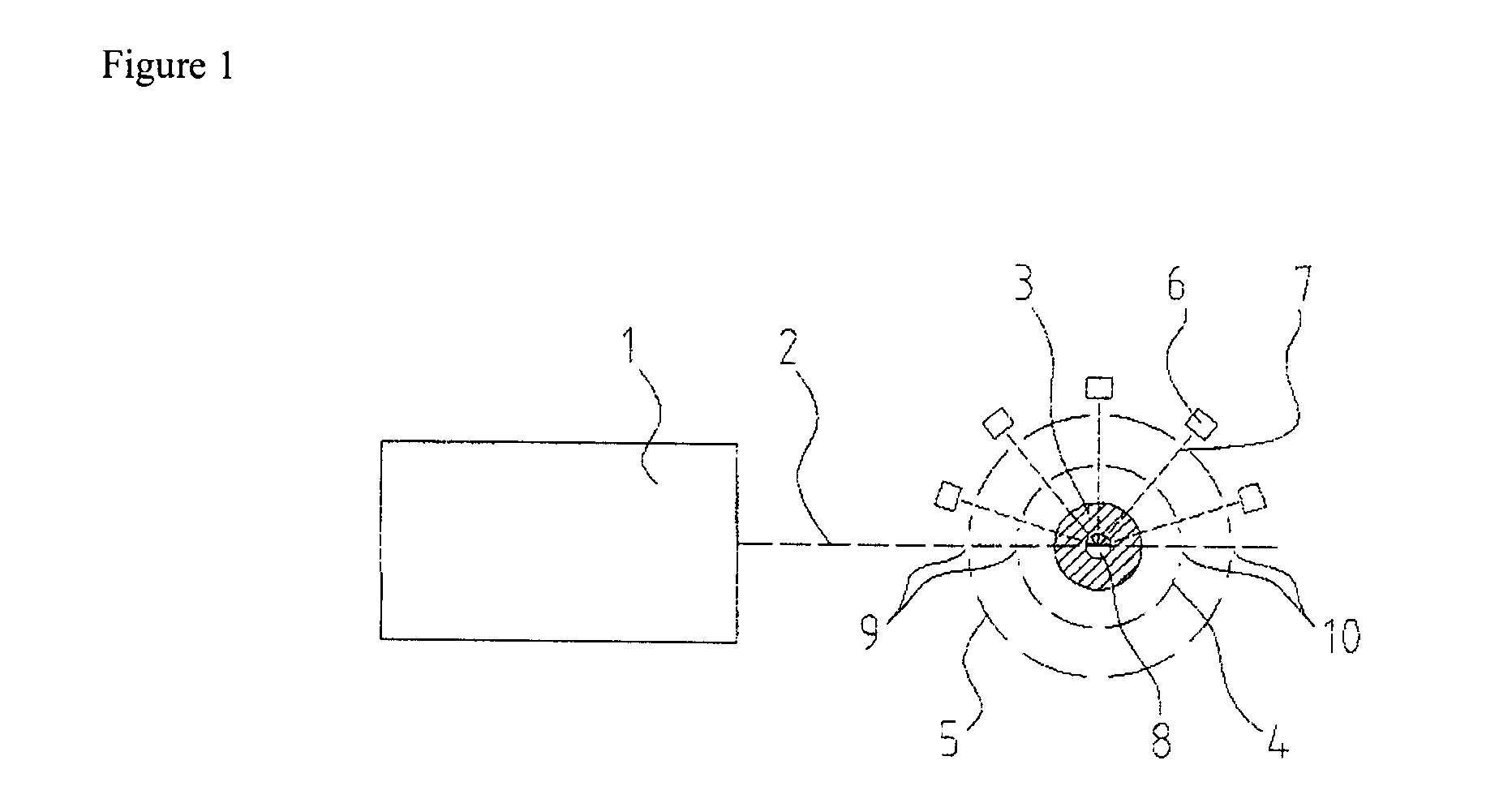
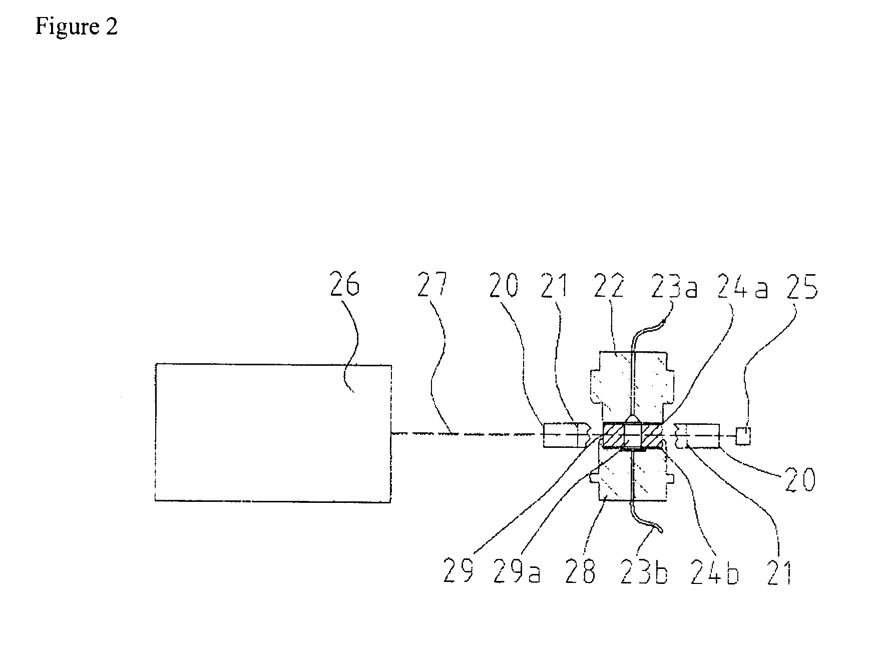
[0022]It is the object of the invention to provide a measuring apparatus for measuring static multi-angle light scattering in an angle range of less than 7° to above 164° in which a translucent measuring cell is used which is filled with a sample or through which a sample flows, and which is illuminated with a laser beam transversely to the filling direction or transversely to the flow direction of the sample, and which does not have the disadvantages described for the apparatuses known from the prior art with regard to the disrupting influence of scattered light from non-observed angle ranges and remissions, and which achieves improvement of the measuring sensitivity.

[0023]This object is achieved by the apparatus according to claim 1 and the method according to claim 10.

[0024]According to the invention, an apparatus for measuring the light scattering properties of a sample in a liquid medium, wherein the liquid medium with the sample is illuminated by a laser beam in a measuring ce...


PUM


Abstract

An apparatus for measuring the light scattering properties of a sample in a liquid medium, wherein the liquid medium with the sample is illuminated by a laser beam in a measuring cell transversely to the direction of filling the liquid medium in the measuring cell or transversely to the flow direction of the liquid medium within the measuring cell, comprising a laser, a cylindrical measuring cell, a first inner aperture system, a second outer aperture system and at least two detectors, wherein the detectors are arranged outside of the second outer aperture system so that they collect the light scattered on the sample within set, different angle ranges, wherein the first inner aperture system and the second outer aperture system are formed and arranged circularly and concentrically around the axis of the measuring cell. Use of the apparatus and a method that makes use of the apparatus are also disclosed.

Description

CROSS-REFERENCE TO RELATED APPLICATIONS[0001]This application claims the benefit of priority to European patent application serial number EP11185620, which was filed on Oct. 18, 2011.TECHNICAL FIELD[0002]The invention relates to an apparatus for measuring the light scattering properties of a sample in a liquid medium, the use of this apparatus and a method for measuring the light scattered on a sample located within a liquid medium.PRIOR ART[0003]Measurement of static light scattering is used in order to characterize (size, mass, shape and structure) molecules or colloidal substances. This is an absolute quantification which goes without any previous calibration or use of standard samples. A sample is illuminated with a laser beam, and the scattered light is measured at different scattering angles.[0004]The principle of light scattering is widespread in nature. It can thus be observed e.g. as the sun sets or when dust particles become visible. Light beams strike a strongly scatterin...

Claims


Application Information

Patent Timeline
IPC IPC(8): G01N21/51
CPCG01N21/51G01N30/74G01N2201/064G01N2021/4711G01N21/53
Inventor FROSE, DIETHELMWELZ, ROLAND
Owner POSTNOVA ANALYTICS
Learn More