Light scattering measurements using simultaneous detection

a simultaneous detection and light scattering technology, applied in the field of particle characteristics measurement, can solve the problems of protein aggregate detection becoming an important issue, degrading measurement, and releasing of separation columns, so as to improve the quantification of the proportion of aggregates, improve the quantification accuracy, and improve the effect of protein based drug therapeutic us

Active Publication Date: 2018-06-26
MALVERN INSTRUMENTS
View PDF21 Cites 6 Cited by
  • Summary
  • Abstract
  • Description
  • Claims
  • Application Information

AI Technical Summary

Problems solved by technology

One major difficulty in applying light scattering to the eluent of a chromatography experiment is that the separation column tends to release or ‘shed’ particles from the column matrix.
These particles are much larger than the chromatographic sample and are likely to degrade the measurement.
The detection of protein aggregates has become an important issue as their presence has a large effect on therapeutic uses of protein based drugs.
Measurement of virus particles by light scattering is often hampered by the presence of trash in the growth media.

Method used


Image

  • Light scattering measurements using simultaneous detection
  • Light scattering measurements using simultaneous detection
  • Light scattering measurements using simultaneous detection

Examples


Embodiment Construction

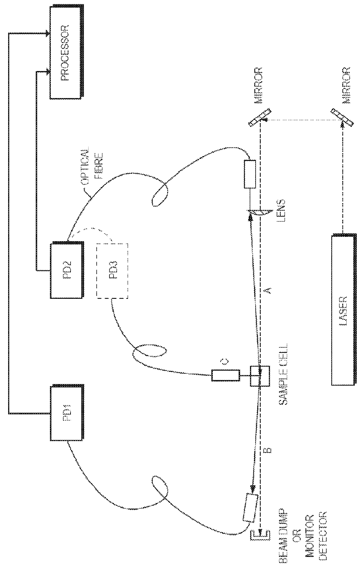
[0020]Referring to FIG. 2, an illustrative embodiment of the invention will now be discussed in more detail. In this embodiment, a laser beam is passed through a sample cell. A photon-counting detector PD1 is preferably positioned behind the sample cell and outside of the optical path of the laser receives backscatter from the cell, such as through an optical fiber. A supplemental detector PD2, which may or may not be a photon-counting detector, is preferably positioned ahead of the sample cell and outside of the optical path of the laser, and receives forward scatter from the cell, such as through an optical fiber. One or more further optional photon-counting detectors (e.g., PD3) can be provided as well, such as to monitor sidescatter through another optical fiber. In one embodiment, PD 1 is simply switched between the PD 1 and PD2 fiber-optic pickups to acquire backscatter and sidescatter.

[0021]It is preferable to position the photon-counting detector to acquire backscattered lig...


PUM

PropertyMeasurementUnit
diameteraaaaaaaaaa
diameteraaaaaaaaaa
refractive indexaaaaaaaaaa

Abstract

Methods and apparatus for measuring particle characteristics are disclosed. In one aspect, an amount of light arising from interaction between light and a suspended sample is detected simultaneously with the acquisition of a photon count from a different direction. At least one measure of particle characteristics can then be derived based at least in part on timing between information from the steps of acquiring and detecting.

Description

CROSS-REFERENCE TO RELATED APPLICATION[0001]This application claims the benefit of U.S. Provisional Application No. 61 / 011,143, filed Jan. 15, 2008, which is herein incorporated by reference.FIELD OF THE INVENTION[0002]This invention pertains to the measurement of particle characteristics, including dynamic measurement of very small particles.BACKGROUND OF THE INVENTION[0003]It is well known on both practical and theoretical grounds that the intensity of light scattered by particles smaller than the wavelength of light is a strong function of particle size. In the Rayleigh Scattering limit where particle radius is below 0.1× wavelength of illumination, the scattered intensity is proportional to particle radius raised to the sixth power and is substantially independent of scattering angle. Above this limit, the angular dependence becomes significant. To describe the scattering in this area, the optical properties of the particle are needed and particle shape also becomes important. T...

Claims


Application Information

Patent Timeline
Patent Type & Authority Patents(United States)
IPC IPC(8): G01N21/00G01N15/14G01N15/00
CPCG01N15/1429G01N15/1427G01N2015/0096G01N2015/0065
Inventor MCNEIL-WATSON, FRASERCONNAH, MALCOLMJACK, ROBERTMCKNIGHT, DAVID
Owner MALVERN INSTRUMENTS
Why Eureka
Try Eureka