Improved method and apparatus for measuring the scattered light signals from a liquid sample

A technique of scattering light and liquid, applied in the direction of measuring device, photometry, optical radiation measurement, etc., can solve the problem of increasing signal background contribution and so on

Active Publication Date: 2011-02-02
WYATT TECH
View PDF18 Cites 7 Cited by
  • Summary
  • Abstract
  • Description
  • Claims
  • Application Information

AI Technical Summary

Problems solved by technology

Additionally, some stray light from the liquid / glass-well interface will reach the detector, thereby increasing the background contribution to the collected signal

Method used


Image

  • Improved method and apparatus for measuring the scattered light signals from a liquid sample
  • Improved method and apparatus for measuring the scattered light signals from a liquid sample
  • Improved method and apparatus for measuring the scattered light signals from a liquid sample

Examples


Embodiment Construction

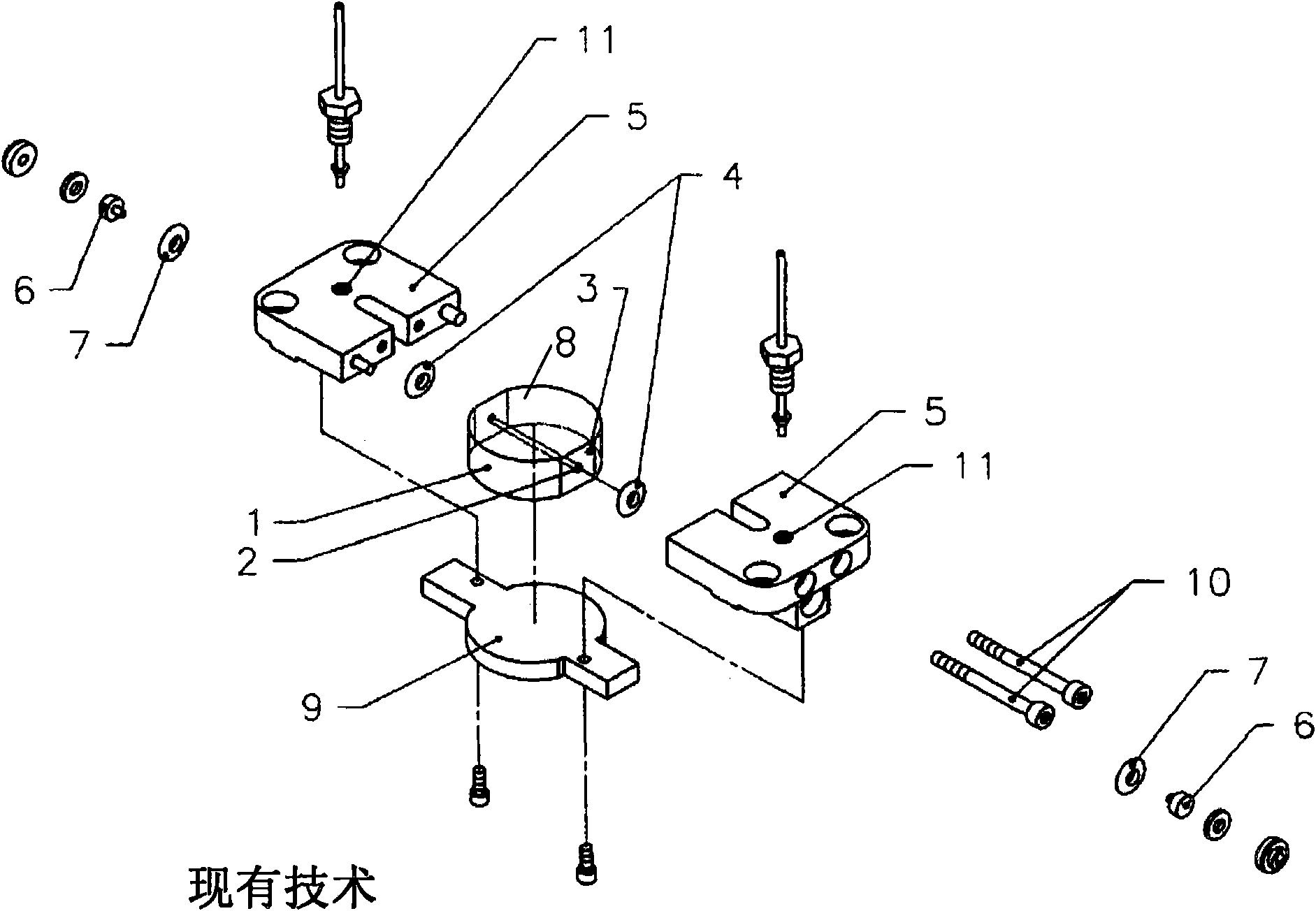
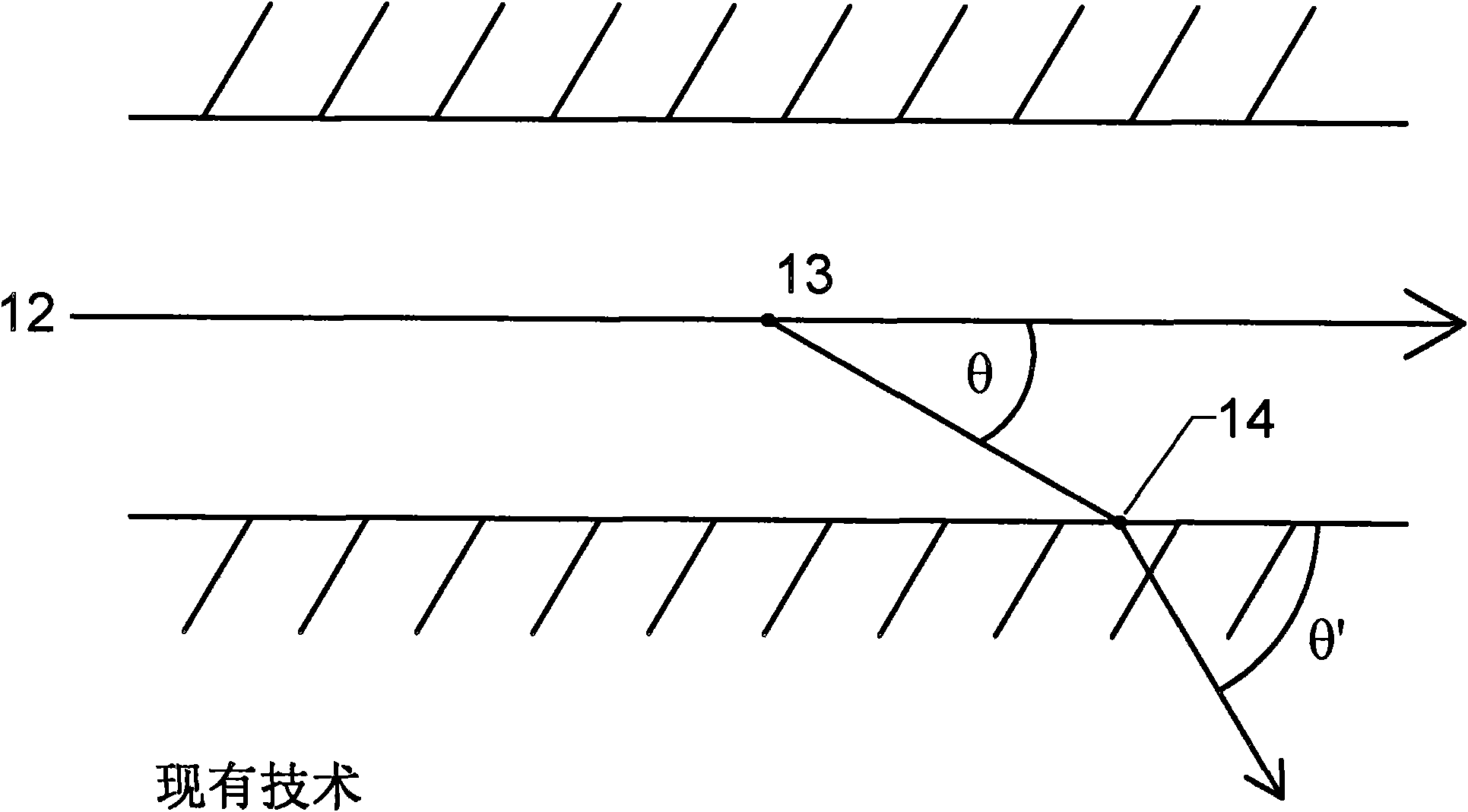
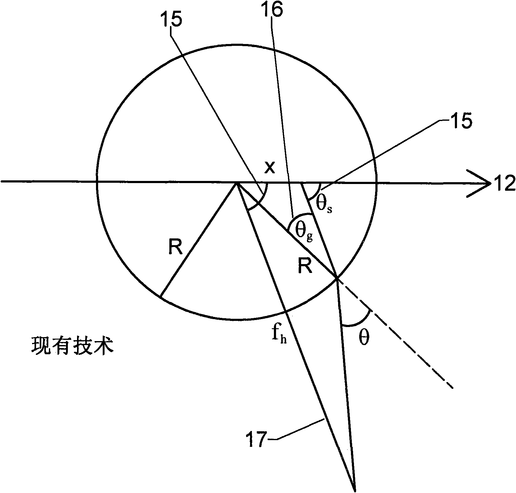
[0026] figure 1 An axial flow cell of the prior art '947 invention is shown along with a typical set of accessories required to maintain its position in a photometer and allow it to measure light scattered from a sample flowing through the cell. The unit 1 is made of a transparent medium such as glass or plastic in the form of a column of radius R, flattened on both sides 3 to allow a seal 4 to be held against. Throughout this specification the composition of the unit will be referred to as glass, however it may be made of any other transparent medium through which a solution flows. A polishing hole 2 passes through the center of the unit and along the diameter, the cross section of the polishing hole 2 can be circular or rectangular, usually in the range of 0.5 to 1.5mm. Two manifolds 5 hold the unit against said seal. The window 6, which is held against the seal 7 by fittings, allows the light beam to pass through. The light, typically from a laser source, is polarized pe...


PUM

PropertyMeasurementUnit
refractive indexaaaaaaaaaa

Abstract

The invention relates to an improved method and apparatus for measuring the scattered light signals from a liquid sample. A sample cell for making light scattering measurements, incorporating an exterior surface acting as both a lateral and vertical lens, is described. This unique structure permits greatly improved measurement of the light scattered by molecules and particles suspended in a fluid contained therein or flowing therethrough while illuminated by a fine light beam incident thereon. The resultant lensed structure of the cell, when integrated into a scattered light photometer and combined with suitable apertures before each scattered light collecting detector, reduces significantly stray light from entering each such detector.

Description

[0001] Related patents and applications [0002] The following inventions and applications relate to methods and apparatus related to the present application. [0003] G.R. Janik and P.J. Wyatt, U.S. Patent No. 5,404,217 (April 4, 1995) "Laserliquid flow cell manifold system and method for assembly." [0004] P.J. Wyatt and G.R. Janik, U.S. Patent No. 5,530,540 (June 25, 1996) "Lightscattering measurement cell for very small volumes." [0005] S.P. Trainoff, U.S. Patent No. 6,426,794 (July 30, 2002) "An optical flow cell incorporating automatic self cleaning." [0006] S.P. Trainoff, U.S. Patent No. 6,452,672 (September 17, 2002) "A self cleaning optical flow cell." [0007] S. Trainoff and P.J. Wyatt, U.S. Patent No. 6,651,009 (November 18, 2003) "Method for determining average solution properties of macromolecules by the injection method." [0008] P.J. Wyatt and M.J. Weida, U.S. Patent No. 6,774,994 (August 10, 2004) "Method and apparatus for determining absolute number de...

Claims


Application Information

Patent Timeline
Patent Type & Authority Applications(China)
IPC IPC(8): G01N21/49G01J1/04G01J1/00
CPCG01N2021/0346G01N2021/4709G01N21/51G01N21/05G01N2021/513
Inventor S·P·特兰奥弗
Owner WYATT TECH
Why Eureka
Try Eureka