System and Method for Visualizing Catheter Placement in a Vasculature

a vasculature and catheter technology, applied in the field of system and method for visualizing catheter placement in the vasculature, can solve the problems of operating limitations that must be accounted for, the uniqueness of imaging modalities, and the complexity of intravascular operations

Inactive Publication Date: 2013-04-25
DIB ULTRASOUND CATHETER
View PDF11 Cites 69 Cited by
  • Summary
  • Abstract
  • Description
  • Claims
  • Application Information

AI Technical Summary

Problems solved by technology

Intravascular operations are always complicated by the simple fact that there is typically no direct visual contact with the instruments that are being used to perform the operation.
These imaging modalities, however, have their respective unique, operational limitations that must be accounted for.

Method used


Image

  • System and Method for Visualizing Catheter Placement in a Vasculature
  • System and Method for Visualizing Catheter Placement in a Vasculature
  • System and Method for Visualizing Catheter Placement in a Vasculature

Examples


Embodiment Construction

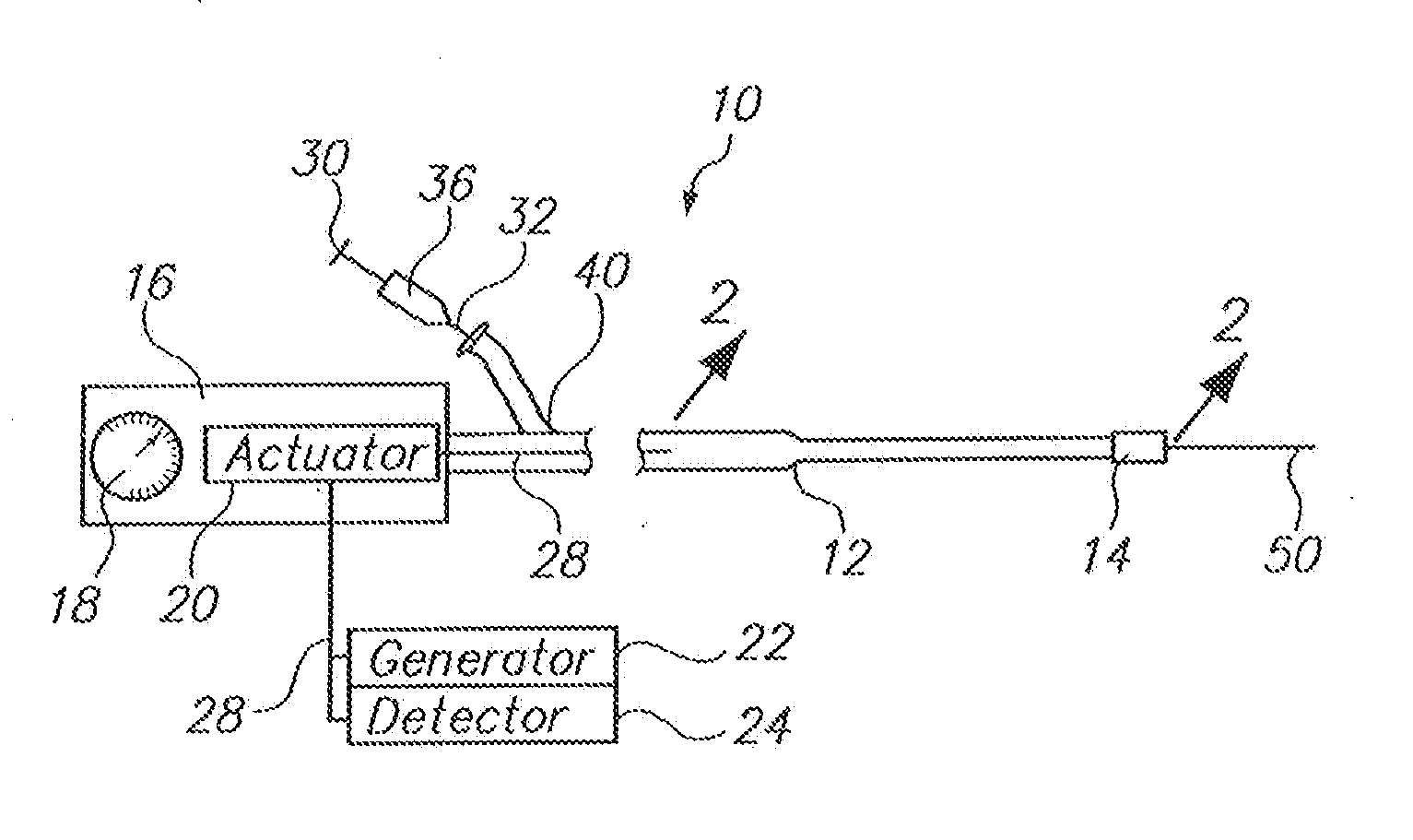
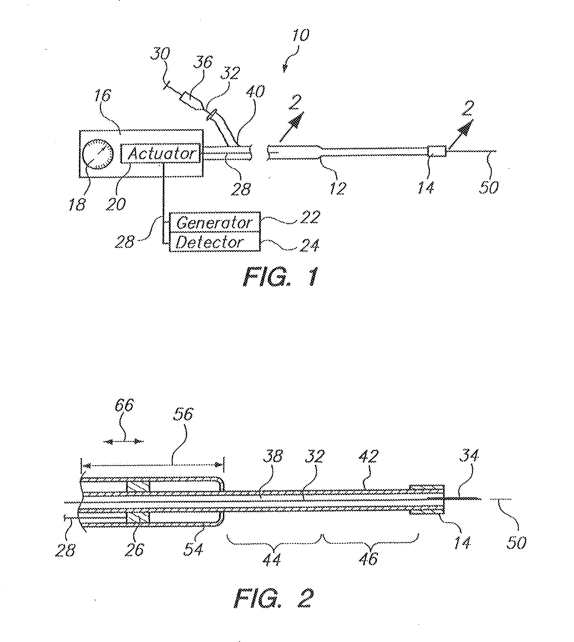
[0028]Referring initially to FIG. 1, a system in accordance with the present invention is shown and is generally designated 10. As shown, the system 10 includes a guide catheter 12 that has a reflective tip 14 at its distal end. The system 10 also has a handle 16 that is mounted at the proximal end of the guide catheter 12, with a dial 18 and an actuator 20 being included as part of the handle 16. Structurally, the dial 18 is connected directly to the actuator 20 for manipulating the actuator 20 during an operation of the system 10. FIG. 1 further indicates that the system 10 includes an energy generator 22 and a detector 24. More specifically, with cross reference to FIG. 2, it is to be appreciated that both the energy generator 22 and the detector 24 are electronically connected to a transceiver 26 via an activation wire 28. It is also to be appreciated that the activation wire 28 can be manipulated by the actuator 20 to move the transceiver 26. Collectively, the energy generator ...


PUM


Abstract

A system for advancing a needle through a vasculature to an injection site at the heart of a patient includes a guide catheter with a reflective distal tip. Also included is an imaging unit that is mounted on the catheter to radiate an energy field. Structurally, a distal portion of the catheter is biased to bend into a predetermined configuration that will position the distal end of the catheter for interception by the energy field. If necessary, coincidence of the reflective tip with the energy field is established by moving the energy field along the length of the guide catheter. With coincidence, the reflective tip reflects a signal that is useful for advancement of the needle 34b from the guide catheter and into the injection site.

Description

[0001]This application is a continuation-in-part application of application Ser. No. 12 / 788,194, titled “SYSTEM AND METHOD FOR VISUALIZING CATHETER PLACEMENT IN A VASCULATURE” filed May 26, 2010 to Nabil Dib, the entire contents of which are hereby incorporated by reference herein.FIELD OF THE INVENTION[0002]The present invention pertains generally to systems for advancing a needle or other secondary instrument through the vasculature of a patient to a treatment site at the heart. More particularly, the present invention pertains to systems that incorporate an imaging modality, such as ultrasound or Optical Coherence Tomography (OCT), to image a needle or other secondary instrument in the vasculature. The present invention is particularly, but not exclusively, useful as a system and method for bringing the energy field of an imaging modality into coincidence with the distal end of a catheter, to monitor the advancement of a needle, wire or other secondary instrument from the distal ...

Claims


Application Information

Patent Timeline
Patent Type & Authority Applications(United States)
IPC IPC(8): A61B5/06A61B8/12
CPCA61B5/061A61B8/12A61M2025/0166A61B2019/5263A61B19/5244A61B2034/2063A61B34/20
Inventor DIB, NABIL
Owner DIB ULTRASOUND CATHETER
Why Eureka
Try Eureka