Methods of Shifting and Bending Rolls in a Rolling Mill

a technology of rolling mill and rolling mill, which is applied in the direction of metal rolling arrangement, counter-pressure devices, manufacturing tools, etc., can solve the problems of high rolling end deflection, high bending force, and affecting the bearing life, and achieves the effect of easy insertion into the mill and good bearing li

Inactive Publication Date: 2013-05-02
I2S
View PDF6 Cites 9 Cited by
  • Summary
  • Abstract
  • Description
  • Claims
  • Application Information

AI Technical Summary

Benefits of technology

[0018]FIGS. 3A-3B illustrate how the bending block incorporates design features which allow for small rotations.
[0019]FIG. 3C shows a free body diagram of a Bending Block illustrating how the Guide Pins counter balance the applied bending force.
[0020]FIG. 4-5 illustrate how the hydraulic circuit is designed to provide good bearing life by ba...

Problems solved by technology

Process needs for roll bending have caused higher bending forces with subsequent higher roll end deflections.
Also, operating practices have changed which have caused the work rolls and intermediate rolls to be shifted perpendicular to the rolling direction for improved shape and edge performance, and these practices have raised important issues with regard to the placement of end bending forces.
Current designs for work roll and intermediate roll chocks generally constrain them to vertical movement which causes the bearing raceways to pinch, gouge, or otherwise behave in ways that reduce the bearing life since the resultant force is not at the bearing center when the roll is shifted.
There is also higher roll end maintenance when the ends have to be re-machined.
Also, some current designs apply hydraulic forces in the positive bending direction only, which is less desirable.
The disclosed method, however, requires a large number of hydraulic cylinders to create the roll bending effect in the work roll and intermediate rolls, which causes maintenance issues and complicated control/operational problems....

Method used


Image

  • Methods of Shifting and Bending Rolls in a Rolling Mill
  • Methods of Shifting and Bending Rolls in a Rolling Mill
  • Methods of Shifting and Bending Rolls in a Rolling Mill

Examples


Embodiment Construction

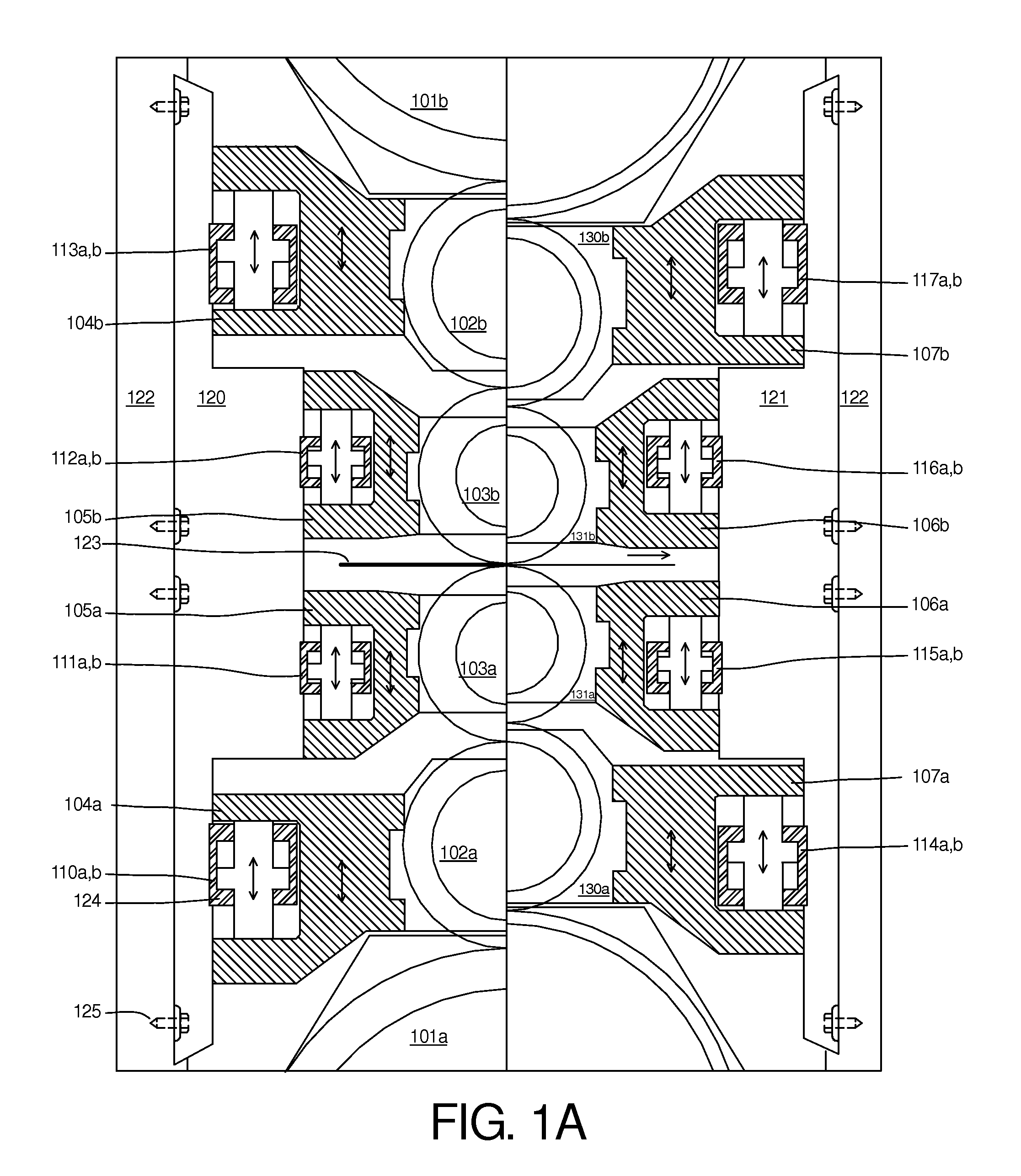
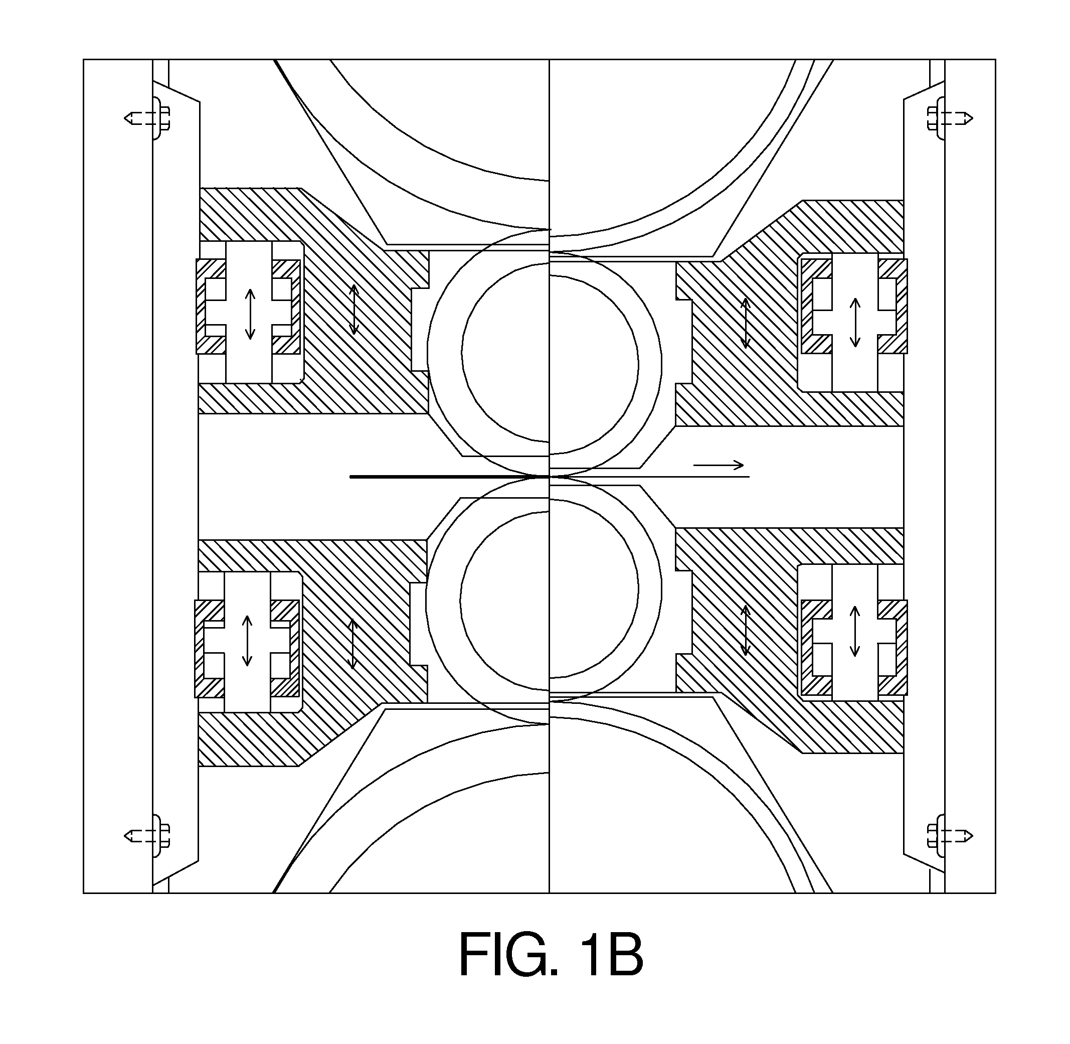
[0023]FIG. 1 is one embodiment of the mill window as conceived in the present invention. For convenience, Table 1 lists the features in the mill window as particularly directed to the roll bending. Other features of the mill are not shown.

TABLE 1FIG. 1101a, bBack Up Roll (Lower and Upper)102a, bIntermediate Roll (Lower and Upper)103a, bWork Roll (Lower and Upper)104a, bLeft Intermediate Roll Bending Block (Lower and Upper)105a, bLeft Work Roll Bending Block (Lower and Upper)107a, bRight Intermediate Roll Bending Block (Lower and Upper)106a, bRight Work Roll Bending Block (Lower and Upper)110a, bLeft Lower Intermediate Roll Bending Block Cylinders111a, bLeft Lower Work Roll Bending Block cylinders112a, bLeft Upper Work Roll Bending Block Cylinders113a, bLeft Upper Intermediate Roll Bending Block Cylinders114a, bRight Lower Intermediate Roll Bending Block Cylinders115a, bRight Lower Work Roll Bending Block Cylinders116a, bRight Upper Work Roll Bending Block Cylinders117a, bRight Upper...


PUM

PropertyMeasurementUnit
Angleaaaaaaaaaa
Forceaaaaaaaaaa
Pressureaaaaaaaaaa

Abstract

An improved roll bending system is described for the work rolls and intermediate rolls in a six high mill. New bending blocks apply improved roll bending forces to the roll chocks, and additionally, are designed to move vertically and rotate, which provide important benefits to maintenance and enhance the rolling operation. Additionally, important related details to the mill operation and bending blocks provide operational improvements during roll changing.

Description

CROSS REFERENCE TO RELATED APPLICATIONS[0001]Not applicable.STATEMENT REGARDING FEDERALLY SPONSORED RESEARCH OR DEVELOPMENT[0002]Not applicable.REFERENCE TO SEQUENCE LISTING, A TABLE, OR COMPUTER PROGRAM LISTING[0003]Not applicable.BACKGROUND OF THE INVENTION[0004](1) Field of the Invention[0005]This invention is directed to vertical stack (2,4,6 high) rolling mill stands used to roll out flat rolled metal products, particularly metals such as steel and aluminum, to a reduced gauge using a pair of work rolls that are between intermediate rolls, which in turn are between backup rolls. Vertical stack rolling mill stands include work rolls, and optionally, intermediate rolls and backup rolls. It is also directed to mills where the rolls are used for controlling the shape of the metal during rolling by applying significant bending forces on the roll ends.[0006](2) Description of Related Art[0007]Currently, in the art, there is a need for improvement in roll bending design so that the be...

Claims


Application Information

Patent Timeline
IPC IPC(8): B21B31/16B21B31/32B21B31/02
CPCB21B31/32B21B29/00B21B31/02
Inventor GUO, REMN-MINARMACK, ALFREDDINELLO, PAULHERBST, JOHNMARTIN, JERRYMIELICKI, WADAW
Owner I2S
Why Eureka
Try Eureka