Heat Removal From Substrates In Vacuum

a vacuum process and substrate technology, applied in the field of wafer processing systems, can solve the problems of affecting the processing efficiency of the wafer, affecting the quality of the wafer, and introducing a significant amount of heat into the specimen, so as to increase or decrease the area of the cooling element exposed.

Inactive Publication Date: 2013-05-02
KLA CORP
View PDF8 Cites 14 Cited by
  • Summary
  • Abstract
  • Description
  • Claims
  • Application Information

AI Technical Summary

Benefits of technology

[0018]In yet another aspect, the amount of surface area of the cooling element exposed to the specimen is controlled by an adjustable aperture. In this manner, the amount of heat removed from the specimen is controlled by adjusting the size of the aperture. In some embodiments, the adjustable aperture is located between the specimen and the cooling plate and includes a thin sheet member akin to a sliding door or a camera shutter that is moved by an actuator (e.g., a piezo actuator) to selectively increase or decrease the area of the cooling element exposed to the specimen. In some embodiments, the shape of adjustable aperture is designed to approximately match the shape of a heat plume across the specimen. In this manner, the spatial distribution of heat absorbed from specimen approximately matches the spatial distribution of heat introduced into specimen. The area of the cooling element exposed to the specimen is adjusted to keep the amount of heat absorbed by the cooling element closely matched to the heat introduced to specimen by incident process energy.

Problems solved by technology

However, direct writing is disadvantageous in that the process is very time-consuming due to the sequential, point-wise writing.
Many semiconductor processing steps, particularly high throughput, electron beam lithography and inspection systems, introduce a significant amount of heat into the specimen.
If the heating is contained locally, it results in local distortion of the specimen at the surface or in the bulk of the material.
However, due to thermal conductivity of the specimen, heat dissipates through the material over time.
This causes changes of dimension of the entire specimen.
In some other examples, dimensional accuracy may be critical, but the process involves only moderate amounts of heat generation that is rapidly transferred away from the specimen.
However, several proposed semiconductor process technologies involve a significant amount of heat generation at the exposure location, in particular, several lithographic processes currently under development.
This effectively precludes many of the conventional options for heat removal.
As lithographic and inspection systems with processes conducted in vacuum are pressed to higher accuracies, heat removal becomes a limiting factor in maintaining placement accuracy of features on a specimen.
Process energy projected onto a specimen generates unwanted heat and thermally induced distortions unless the heat is removed.
This is particularly challenging in a deep vacuum environment.

Method used


Image

  • Heat Removal From Substrates In Vacuum
  • Heat Removal From Substrates In Vacuum
  • Heat Removal From Substrates In Vacuum

Examples


Embodiment Construction

[0031]Reference will now be made in detail to background examples and some embodiments of the invention, examples of which are illustrated in the accompanying drawings.

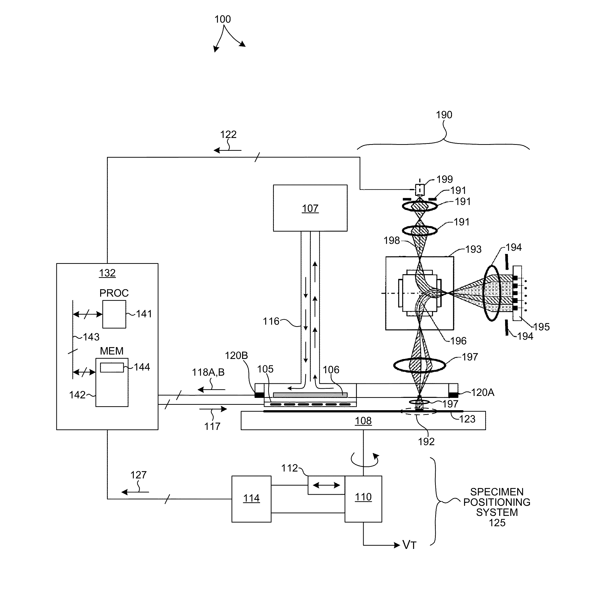
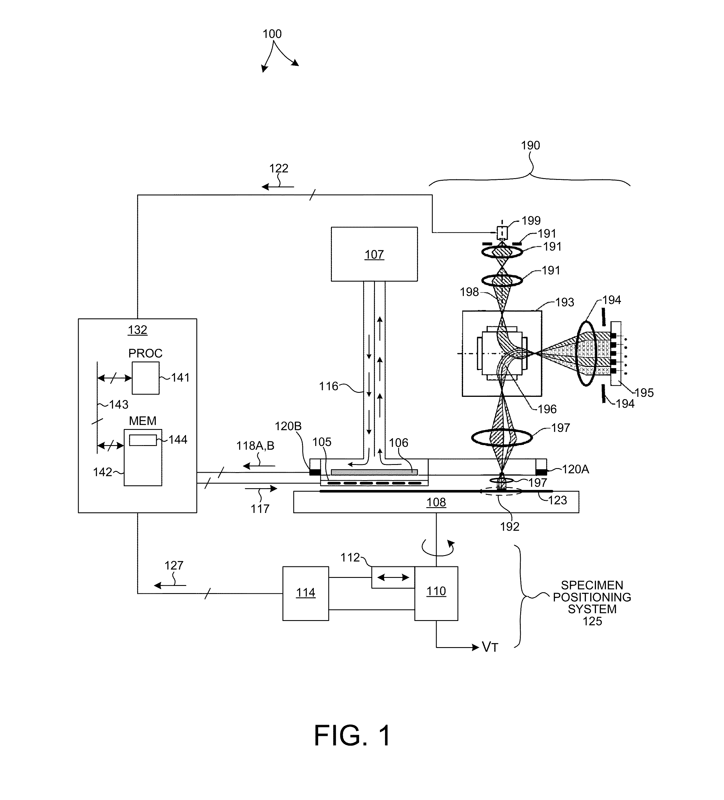
[0032]FIG. 1 is a simplified schematic view of one embodiment of a semiconductor processing system 100 that may be used to perform specimen cooling methods described herein. In the illustrated embodiment electrons are projected onto a specimen 123. The system 100 includes specimen positioning system 125 that is configured to support and move specimen 123 during projection of electrons onto the specimen. The system 100 also includes projection subsystem 190. Projection subsystem 190 is configured to project an electron beam onto specimen 123 while specimen positioning system 125 is moving specimen 123. Projection subsystem 190 includes electron source 199, illumination electron-optics 191, magnetic prism 193, objective electron-optics 194, dynamic pattern generator (DPG) 195, and projection electron-optics 197.

[0033]El...


PUM


Abstract

Systems and methods to precisely balance the amount of heat removed from a specimen with the amount of heat generated during processing are presented. In some embodiments, the heat introduced into the specimen is rapidly removed by a temperature controlled cooling element via radiative heat transfer. In some embodiments, a heating element is disposed between the specimen and the cooling element. The heating element is controlled to precisely balance the amount of heat removed from the specimen with the amount of heat generated. A control signal is generated based on the amount of process energy known apriori. The control signal may also be based on an indication of a temperature of the specimen. In some embodiments, an adjustable aperture is employed to change the surface area of the cooling element exposed to the specimen, and thus control the amount of heat absorbed from the specimen by the cooling element.

Description

CROSS REFERENCE TO RELATED APPLICATION[0001]The present application for patent claims priority under 35 U.S.C. §119 from U.S. provisional patent application Ser. No. 61 / 552,088, entitled “Radiative Heat Removal From Substrates In Vacuum,” filed Oct. 27, 2011, the subject matter of which is incorporated herein by reference.TECHNICAL FIELD[0002]The described embodiments relate to systems for wafer processing, and more particularly to processes performed in vacuum.BACKGROUND INFORMATION[0003]Semiconductor devices such as logic and memory devices are typically fabricated by a sequence of processing steps applied to a specimen. The various features and multiple structural levels of the semiconductor devices are formed by these processing steps. For example, lithography among others is one semiconductor fabrication process that involves generating a pattern on a semiconductor wafer. Additional examples of semiconductor fabrication processes include, but are not limited to, chemical-mechan...

Claims


Application Information

Patent Timeline
Patent Type & Authority Applications(United States)
IPC IPC(8): G05D23/19F25B29/00
CPCH01J37/20H01L21/67109H01J2237/2001G05D23/19H01J2237/3175F25B29/00H01J2237/31701
Inventor ZYWNO, MAREKHALE, LAYTON CARTER
Owner KLA CORP
Why Eureka
Try Eureka