Tolerance ring for torque transmission device

Active Publication Date: 2013-05-02
TOGO SEISAKUSYO
View PDF23 Cites 16 Cited by
  • Summary
  • Abstract
  • Description
  • Claims
  • Application Information

AI Technical Summary

Benefits of technology

The patent text describes a way to prevent parts from collapsing and causing issues in a device. This is achieved by making the parts rigid enough to balance in their gap, which prevents them from appearing too elongated or too short. This technique also prevents parts from being eccentric, which can cause issues in the transmission of power.

Problems solved by technology

In this way, eccentricity between the axial members S1 and S2 is undesirable since it causes an increase in slip torque in one area in the circumferential direction and causes a decrease in slip torque in another area, and thus makes surface pressure remarkably unevenness and leads to positional displacement of the inner axial member S1 and / or the outer axial member S2.

Method used


Image

  • Tolerance ring for torque transmission device
  • Tolerance ring for torque transmission device
  • Tolerance ring for torque transmission device

Examples


first embodiment

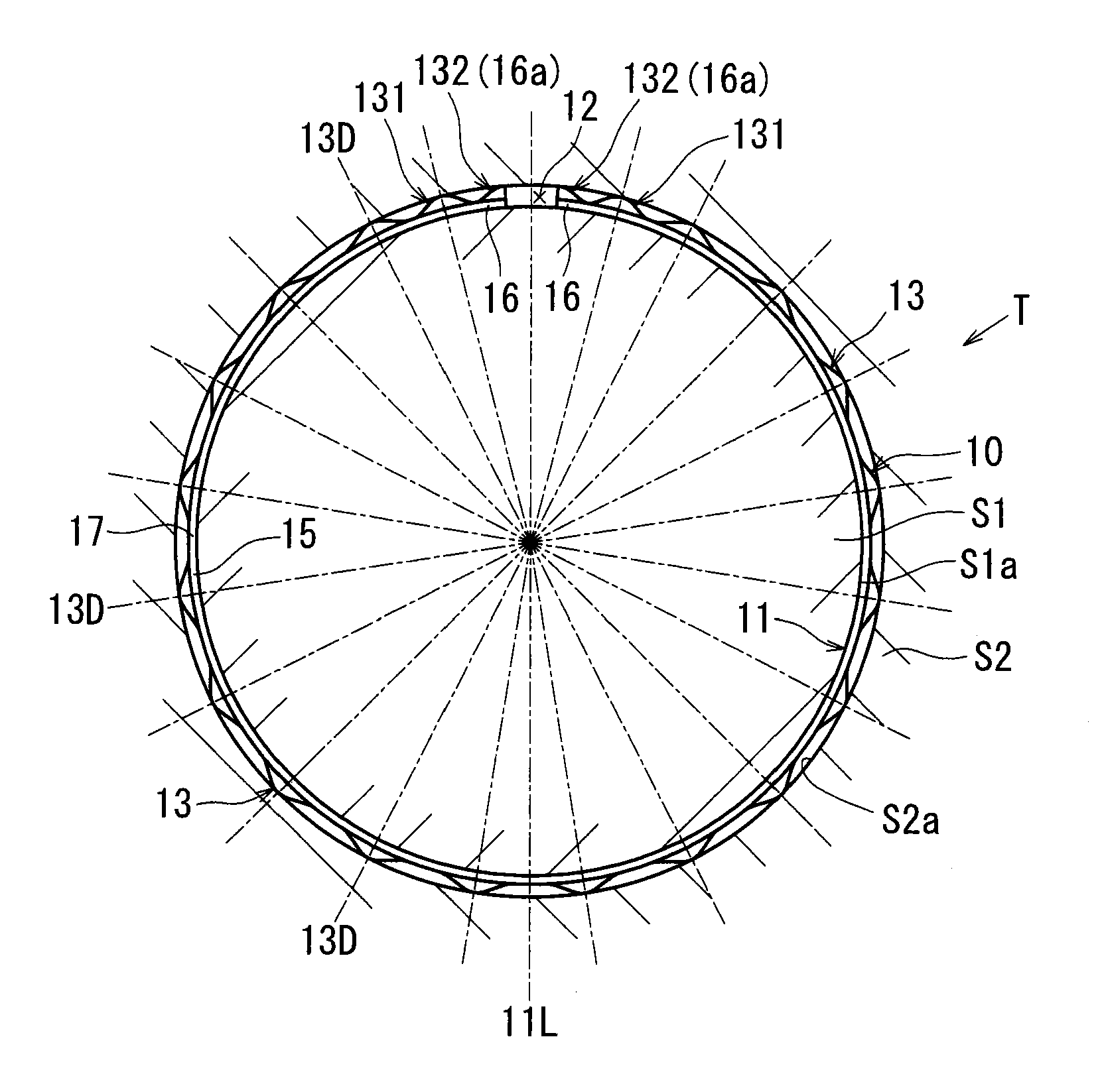
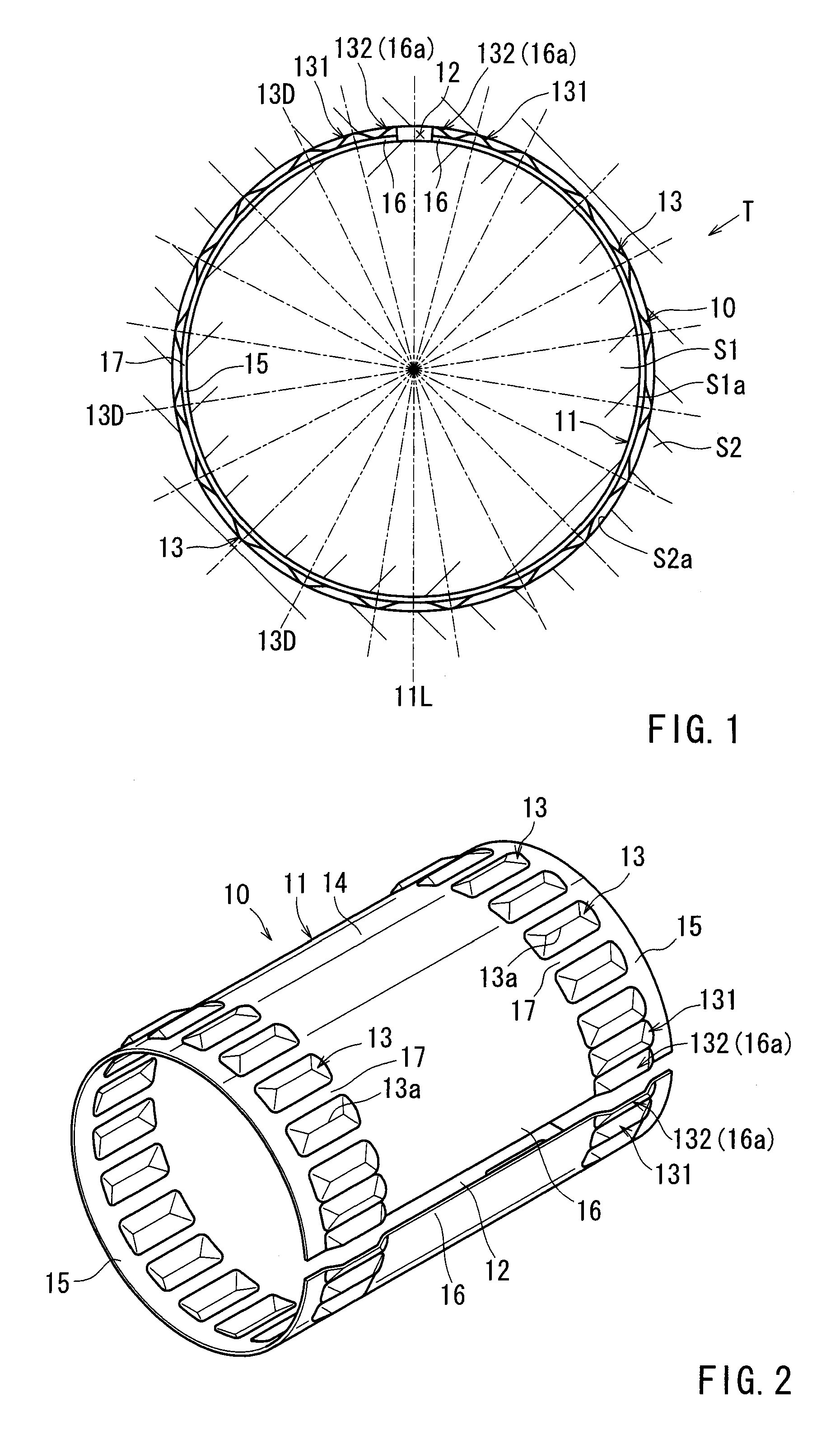
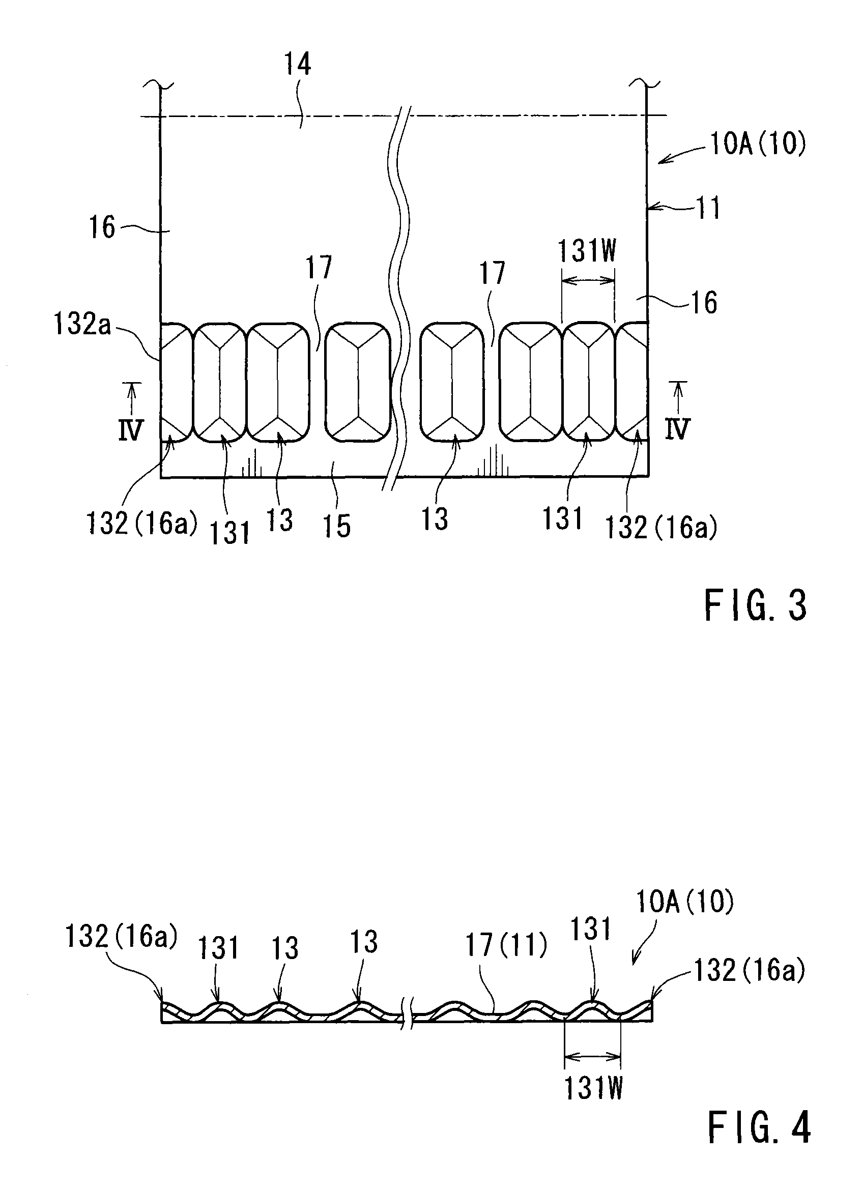
[0044]A first embodiment will be described. FIG. 1 is a cross-sectional view showing a torque transmission device. FIG. 2 is a perspective view of the tolerance ring. FIG. 3 is a top view of the developed same tolerance ring. FIG. 4 is a cross-sectional view along line IV-IV in FIG. 3.

[0045]With respect to a tolerance ring 10 used for a torque transmission device of this embodiment, one and a half of reinforced protrusions 131 and 132 are formed at each edge area 16 of the ring body 11 symmetrically about the gap 12. The reinforced protrusion 131 has a narrower width 131W (see FIGS. 3 and 4) than the width 13W of the standard protrusions 13 (see FIGS. 29 and 30). Because of this configuration, rigidities of the reinforced protrusions 131 are higher than those of the standard protrusions 13. In addition, the reinforced protrusions 131 each have the same length 13L with the length 13L of the standard protrusions 13 (see FIGS. 29 and 31). Moreover, the reinforced protrusions 131 each h...

fourth embodiment

[0059]A fourth embodiment will be described. This embodiment corresponds to the conventional art with some changes. FIG. 7 is a cross-sectional view of the torque transmission device. FIG. 8 is a top view of the developed same tolerance ring 10. FIG. 9 is a cross-sectional view along line IX-IX in FIG. 8.

[0060]As shown in FIGS. 7-9, the tolerance ring 10 of this embodiment certain features are formed in a similar manner as the first embodiment (see FIGS. 1-4). At the pair of the edge areas 16 near the gap 12 of the ring body 11 of the conventional art (see FIGS. 28-30) the reinforced protrusions 131 and the edge reinforcing portions 132 are formed symmetrically about the gap 12. The number of the standard protrusions is reduced from twenty-eight in the conventional art (see FIG. 28) to twenty-five. The twenty-five standard protrusions 13 are arranged regularly and continuously in a circumferential direction in the same way as the conventional art (see FIGS. 29 and 30).

[0061]A fifth ...

sixth embodiment

[0063]A sixth embodiment will be described. This embodiment corresponds to the conventional art with some changes. FIG. 12 is a top view of the developed tolerance ring. FIG. 13 is a cross-sectional view along line XIII-XIII in FIG. 12.

[0064]As shown in FIGS. 12 and 13, in the tolerance ring 10 of this embodiment, the pair of the standard protrusions 13 close to the gap 12 of the conventional art (see FIGS. 26-31) are replaced with reinforced protrusions 133. The reinforced protrusions 133 each have length 133L longer than length 13L of the standard protrusions 13 (see FIGS. 29 and 31). Due to this configuration, rigidities of the reinforced protrusions 133 are increased compared to the rigidities of the standard protrusions 13. The reinforced protrusions 133 are formed to have the width 13W same with the width 13W of the standard protrusions 13 (see FIGS. 29 and 30). The reinforced protrusions 133 are formed to have the same height 13H as the height 13H of the standard protrusions ...


PUM


Abstract

This tolerance ring, which is for a torque transmission device, preferably has a ring body that comprises an elastic plate and is roughly a hollow cylindrical shape having a pair of edges that extend in the axial direction. The ring body has: a plurality of protrusions that are arranged along the peripheral direction and preferably protrude in the radial direction; a first region having a number of the protrusions including the pair of protrusions adjacent to the pair of edges; and that is positioned at the diametrically opposite side from the first region. The pair of protrusions has the same rigidity as one of the protrusions of the second region.

Description

PRIORITY CLAIM[0001]The present application is a National Phase entry of PCT Application No. PCT / JP2011 / 069742, filed Aug. 31, 2011, which claims priority from Japanese Patent Application No. 2010-197573, filed Sep. 3, 2010, the disclosures of which are hereby incorporated by reference herein in their entirety.FIELD OF THE INVENTION[0002]The present invention relates to tolerance rings for torque transmission devices.DESCRIPTION OF THE RELATED ART[0003]A conventional example will be described. FIG. 26 is a cross-sectional view of a conventional torque transmission device. As shown in FIG. 26, the torque transmission device T has an inner axial member S1, an outer axial member S2, which are placed concentrically, and a tolerance ring 10 fitted in an annular space between the axial members S1 and S2. The inner axial member S1 has an outer peripheral surface S1a in a hollow cylinder shape having a predetermined outside diameter. Also, the outer axial member S2 has an inner peripheral s...

Claims


Application Information

Patent Timeline
IPC IPC(8): F16D7/02
CPCF16D1/0835F16D7/021F16C35/02F16D7/02F16D2001/062
Inventor NAKAMURA, YUJIKONDO, SATORU
Owner TOGO SEISAKUSYO
Why Eureka
Try Eureka