Eureka AIR delivers breakthrough ideas for toughest innovation challenges, trusted by R&D personnel around the world.

Shielded encapsulating structure and manufacturing method thereof

Active Publication Date: 2013-05-02
STMICROELECTRONICS SRL
View PDF8 Cites 17 Cited by
  • Summary
  • Abstract
  • Description
  • Claims
  • Application Information

AI Technical Summary

Benefits of technology

The patent is about a new way to make a shielded encapsulating structure and its manufacturing method. This new method helps to solve problems in the current methods.

Problems solved by technology

The embodiment of FIG. 1 has, however, a relatively high manufacturing cost, due to the need to form the through vias.
This further embodiment presents, however, the disadvantage of requiring a machined cap (comprising a recess), which has a cost higher than the cost of a planar cap (for example, of the type shown in FIG. 1).
In particular, the cost is typically highest in the case of packages for hermetically sealed pressure sensors, which require caps with a particular shielding of the measurement vias.
In addition, due to manufacturing reasons, the depth of the recess is limited, and thus the maximum height (measured along an axis orthogonal to the plane of lie of the substrate) of the internal cavity of the package obtained is consequently limited.

Method used


Image

  • Shielded encapsulating structure and manufacturing method thereof
  • Shielded encapsulating structure and manufacturing method thereof
  • Shielded encapsulating structure and manufacturing method thereof

Examples


Embodiment Construction

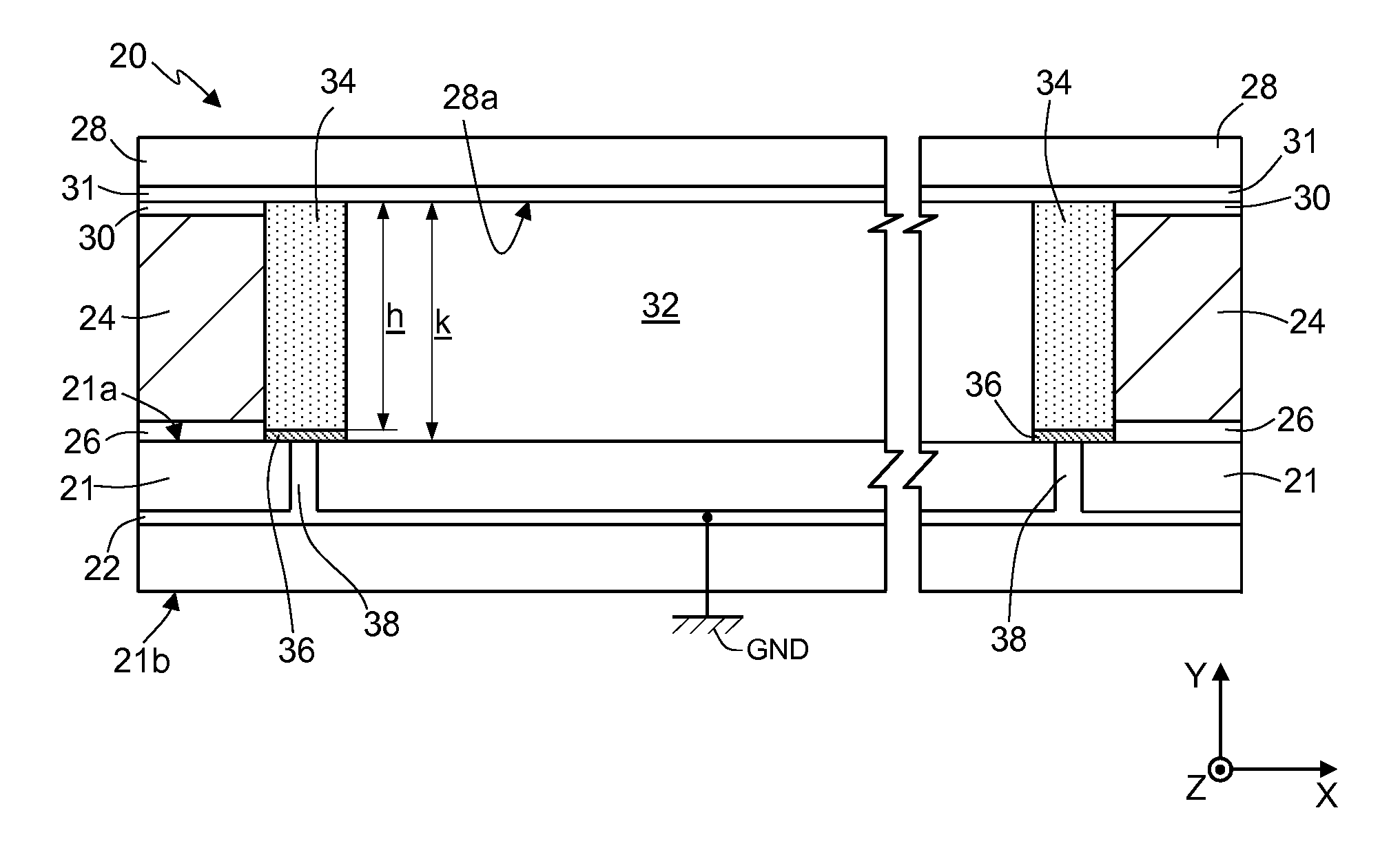
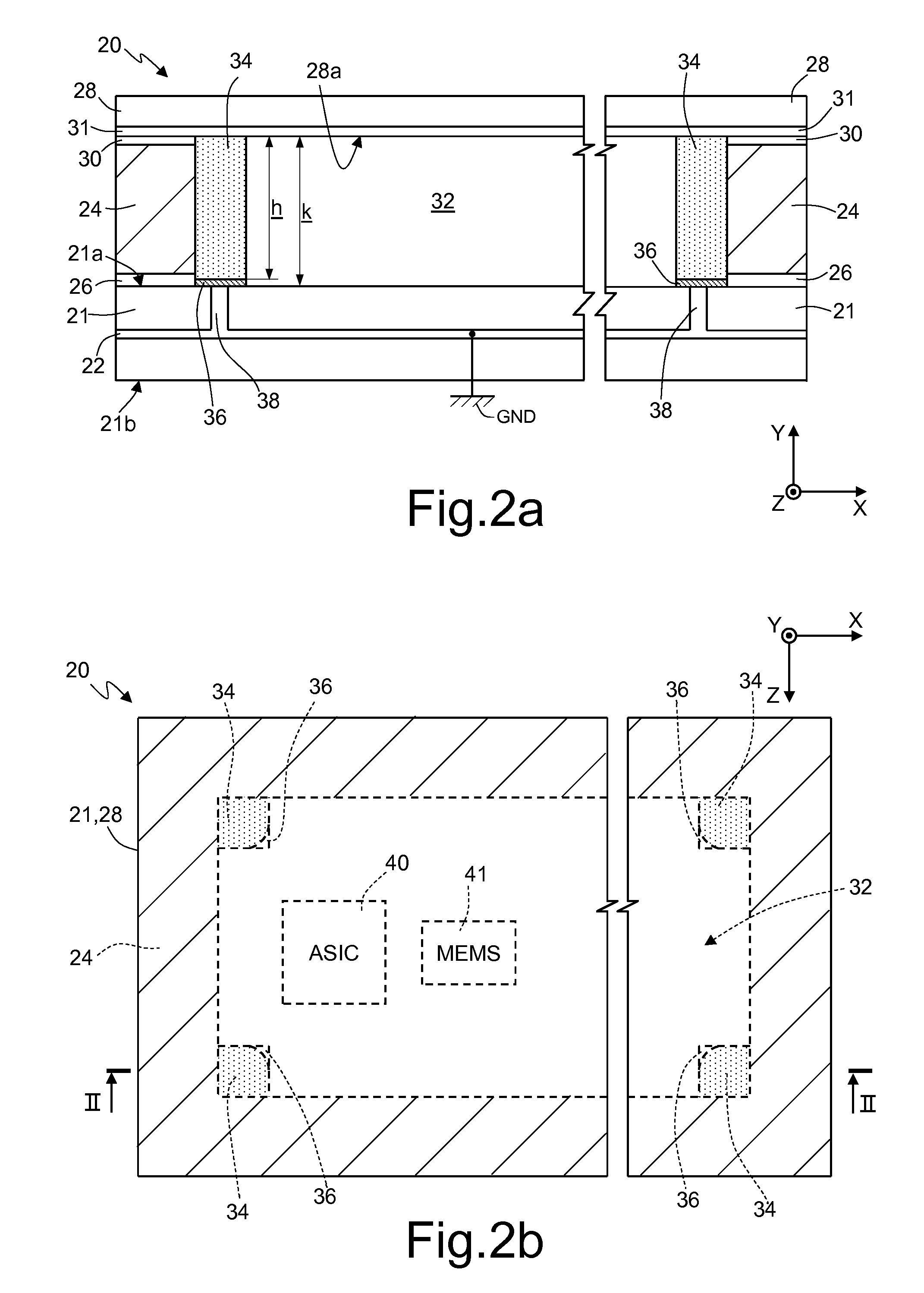
[0027]FIG. 2a shows, in cross-sectional view along a line of section II-II of FIG. 2b, an encapsulating structure, or package 20 according to one embodiment of the present disclosure. FIG. 2b shows the package 20 of FIG. 2a in top plan view.

[0028]The package 20 comprises a substrate 21 (lying in a plane XZ), comprising one or more metal layers 22 (only one of which is shown by way of example in FIG. 2a), which extend on the inside of the substrate 21 or in areas corresponding to surface regions of the substrate 21.

[0029]One of said metal layers 22 extends throughout the extension of the substrate 21, and is connected to a ground plane GND of the package 20. According to one embodiment, in order to form a complete shield, the metal layer 22 extends throughout the extension of the substrate 21. Other embodiments, in which the metal layer 22 extends only partially in the substrate 21 are, however, possible.

[0030]The substrate 21 moreover houses one or more electrical and / or electronic ...


PUM


Abstract

One or more embodiments are directed to encapsulating structure comprising: a substrate having a first surface and housing at least one conductive pad, which extends facing the first surface and is configured for being electrically coupled to a conduction terminal at a reference voltage; a cover member, set at a distance from and facing the first surface of the substrate; and housing walls, which extend between the substrate and the cover member. The substrate, the cover member, and the housing walls define a cavity, which is internal to the encapsulating structure and houses the conductive pad. Moreover present inside the cavity is at least one electrically conductive structure, which extends between, and in electrical contact with, the cover member and the conductive pad for connecting the cover member electrically to the conduction terminal.

Description

BACKGROUND[0001]1. Technical Field[0002]The present disclosure relates to a shielded encapsulating structure (or package) and to a manufacturing method thereof, and in particular to an encapsulating structure for a MEMS microphone.[0003]2. Description of the Related Art[0004]The package of microelectromechanical systems (MEMS), such as, for example, microphones and pressure sensors, provides an electrical shielding between the region of space inside the package itself and the external environment in which the package is set. Said shielding has the function of eliminating, or at least reducing, any possible drifts in the signal of the sensor caused by interference due to electrostatic charges, for example generated by magnetic fields external to the package. Basically, said package operates according to the known principle of the Faraday cage.[0005]In addition, the package also performs a function of mechanical protection of the sensor, albeit providing, if necessary, a certain degre...

Claims


Application Information

Patent Timeline
IPC IPC(8): H01L23/60H01L21/56
CPCB81B7/0064H04R1/021H04R1/04H04R2201/029H04R19/04H04R31/006H04R2201/003H04R19/005H01L2224/48137H01L2224/48091H01L2924/00014B81B2201/0257H05K9/0009
Inventor FONTANA, FULVIO VITTORIOGRAZIOSI, GIOVANNIGRITTI, ALEX
Owner STMICROELECTRONICS SRL
Why Eureka
Eureka Blog
Learn More