Carburetor Choke Mechanism

Active Publication Date: 2013-05-02
MIKUNI CORP
View PDF19 Cites 0 Cited by
  • Summary
  • Abstract
  • Description
  • Claims
  • Application Information

AI Technical Summary

Benefits of technology

The present invention provides a carburetor choke mechanism that is compact and can quickly open and close the choke valve. This allows for more effective and quicker engine starting. The mechanism is simple and easy to operate.

Problems solved by technology

Consequently, a structure of the whole choke mechanism must be enlarged, and since the stroke is large, it takes time to open the choke valve 31, and it will also result in causing deterioration of fuel consumption.

Method used


Image

  • Carburetor Choke Mechanism
  • Carburetor Choke Mechanism
  • Carburetor Choke Mechanism

Examples


Embodiment Construction

[0028]Hereinafter, embodiments of the present invention will be described with reference to accompanying drawings.

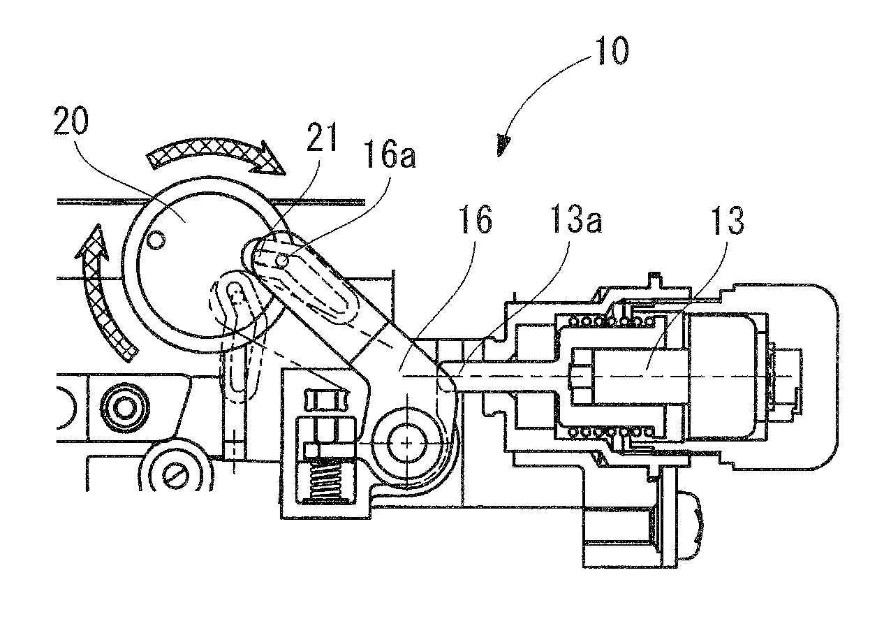
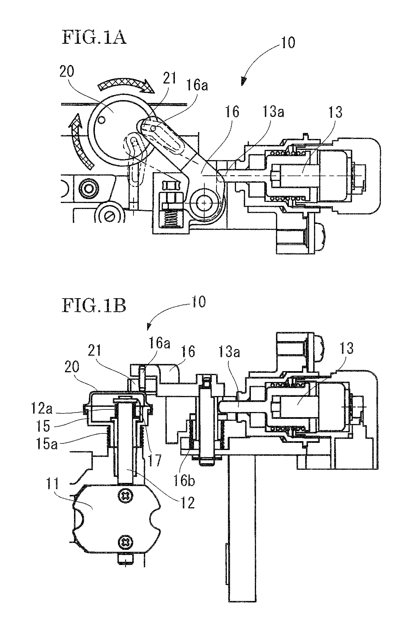
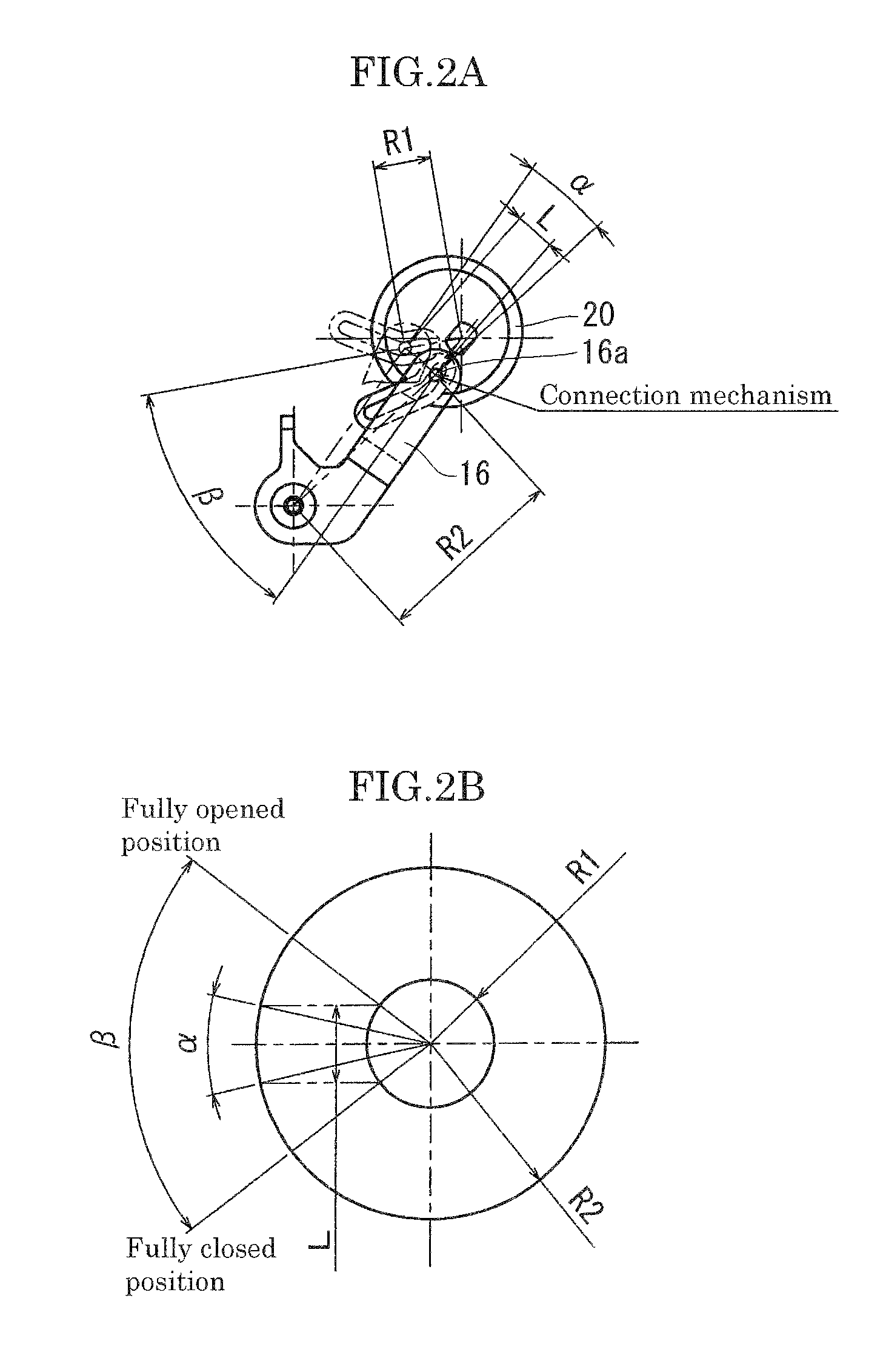
[0029]FIG. 1 is a figure showing a carburetor choke mechanism according to the present invention, and FIG. 1A is a plan view, and FIG. 1B is a front view.

[0030]A driving source of this choke mechanism 10 is an electric type heat source actuator 13. This electric type heat source actuator 13 is provided inside with a heater element which is not shown, and is configured so that internal wax may be distended when a temperature of this heater element rises, and thereby, a tip part 13a may be moved forward. After that, if electric conduction to the heater element is stopped and a temperature of the element descends, the tip part 13a will return to the original position.

[0031]The tip part 13a of the electric type heat source actuator 13 abuts on a connection lever 16, and transfers a motive power thereto. The connection lever 16 is configured so that one end thereof is connect...


PUM


Abstract

A carburetor choke mechanism comprising: an actuator linearly expanded and contracted based on a temperature change; a connection lever which is connected to a rotation axis at one end, and rotates based on receiving a thrust of the actuator; a choke lever which is connected with the other end of the connection lever, and receives a rotatory force; and a valve shaft where a choke valve is fixed to one end thereof, and a valve shaft lever which receives a transfer of a rotatory force from the choke lever is provided on the other end thereof, wherein the choke lever has a bottomed cylindrical shape covering an outer circumference of the valve shaft lever, and the valve shaft penetrates a bottom thereof, and is provided rotatably, and a connection mechanism between the connection lever and the choke lever is provided inside a cylindrical outer periphery of the choke lever.

Description

BACKGROUND OF THE INVENTION[0001]1. Field of the Invention[0002]The present invention relates to a carburetor choke mechanism which controls a degree of opening of a choke valve automatically.[0003]2. Related Background of the Invention[0004]A choke mechanism is used in order to enhance an air-fuel ratio temporarily at the time of engine start-up. Although a choke valve has been opened and closed by manual operation heretofore, increasing has been recently an automatic choke type where the degree of opening of the choke valve provided in a carburetor has been made to be dependent on a change of an engine temperature for achieving stabilizing of a warming-up operation, and enhancing in fuel efficiency (for example, Patent Document 1).[0005]FIG. 7 is a side view showing a conventional choke mechanism shown in Patent Document 1. In addition, FIG. 8 is a sectional view of FIG. 7, and FIG. 8A shows an A-A cross section, and FIG. 8B shows a B-B cross section.[0006]The choke mechanism desc...

Claims


Application Information

Patent Timeline
IPC IPC(8): F02M1/10
CPCF02M1/10
Inventor KIN, CHIREISUGIZAKI, AKIHIRO
Owner MIKUNI CORP
Why Eureka
Try Eureka